


21
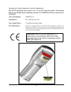
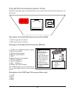
The M71V2 Communications Ports
The M71V2 has three types of communications ports on the bottom of the unit. The three ports are
shown here.
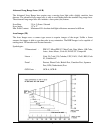
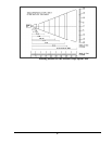
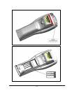
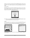
Description of the Infra-Red Detector Array Port (IrDA)
1. IrDA in (right side of window)
2. IrDA out (left side of window)
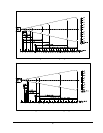
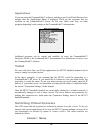
Description of the RJ-45 10 Pin Connector (RS-232)
1. 5 VDC (out to handheld tethered scanner)
2. RxD (in to terminal)
3. TxD (out from terminal)
4. RTS (out from terminal)
5. GND
6. Battery Charge (in to terminal)
7. CTS (in to terminal)
8. UDC+ (USB data +)
9. UDC – (USB data -)
10. Battery Out (from terminal)
Note: the Battery Out is only active when the unit
is set to IrDA w/RS232 Scanner or IrDA w/RS232
Comms
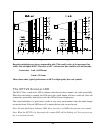
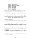
Description of the USB Type II Connector (Slave only)
1. 5 VDC
2. Data -
3. Data +
4. GND
10 9 8 7 6 5 4 3 2 1
4 3
1 2
1 2
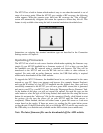
Note:
A standard 8
-pin
Ethernet connector
can be used to
connect the M71V2 to
an RS-232 serial port
printer. In this case
the 2 outside pins (1
and 10) are not
connected. Use the
chart and example on
th
e right to determine
the pin
-
out.
1. RxD (in to terminal)
2. TxD (out from
terminal)
3. RTS (out from
terminal)
4.
GND