


MaxLoader User’s Guide
42
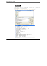
V0007111100XXXNXXXHHLHXXN*
V0008111110XXXNXXXLHHLXXN*
C124E*<ETX>8646
STX The fuse map begins with an ASCII STX character (02 HEX)
Design Specification This item is user specific. While no format rules apply,
certain information, such as user’s name, company, design
date, part designation, revision and device part number,
should be entered. This field is illustrated by an asterisk
(*).
QP Specifies the number of pins in the devices.
QF Specifies the number of JEDEC fuses in the devices.
L The fuse list fields contain the state of all fuse links in the
devices. The starting fuse number follows the L specifying
the field type. The fuse list that follows contains a zero (0)
for each intact link and a one (1) for each blown link. An
L field is generated for each product term in the device.
C The checksum field contains the 16-bit sum of the link
stated in the 8-bit words.
ETX The fuse map ends with an ASCII ETX character (03
HEX).
Sum Check A 16-bit sum of the ASCII values of the characters from
STX to ETX inclusive. The sum check follows the ETX.
NOTE: LOGIC Compilers For PLD Devices: Software is available to help the
engineer develop designs using PLDs. Software tools called logic assemblers or
compilers translate a design file written in high-level language into a fuse
pattern stored in a JEDEC file. JEDEC files are produced by almost all PLD
development software’s and are accepted by the MaxLoader programmer.
There are many commercial software packages available to help you design
using PLDs.