


MaxLoader User’s Guide
89
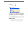
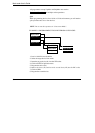
Now, you have two 8-bit EPROMs that have been programmed. The first
EPROM (#1) contains all the even address or low bytes and the second (#2)
device contains all the odd address or high bytes.
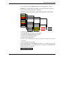
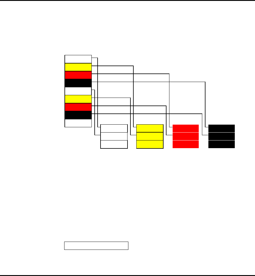
EXAMPLE 2: PROGRAMMING FOUR 8-BIT EPROMS AS FOLLOWS:
Byte $0000 Byte $0001 Byte $0002 Byte $0003
Byte $0004 Byte $0005 Byte $0006 Byte $0007
Byte $0000
Byte $0001
Byte $0002
Byte $0003
Byte $0004
Byte $0005
Byte $0006
Byte $0007
:
: : : :
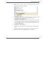
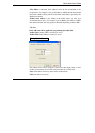
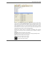
1. Select the target EPROM.
2. Load the HEX file (32-bit file) into the buffer.
3. Insert the first EPROM (#1) into the socket.
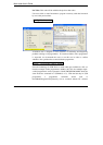
4. Invoke Word 0 in Split Data menu.
5. Program the mounted device.
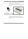
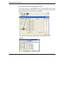
6. Remove the programmed device (#1) and insert the second device (#2) into
the socket.
7. Follow the same steps as above.
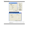
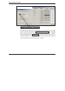
After programming the 4th EPROM with Word 3, you will have four 8-bit
programmed EPROMs. The original file (32-bit) is split into four EPROMs that
contain 8-bit data in each device.
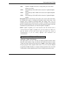
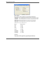
Config Option / Address