


MaxLoader User’s Guide
77
NOTE: Due to hardware’s limitation, Vector Test is only implemented on 24-
pin or less devices.
During the vector test, TopMax applies high and low signals to the input pins of
a tested PLD and observes signals at the output pins. The output results are
compared to the expected results from the test vectors. Any difference will
show up as an error message.
The following are valid characters for test vectors:
0 Apply input logic low (Vil) to an input pin
1 Apply input logic high (Vih) to an input pin
C Clock an input pin (Vil, Vih, Vil)
F Float pin
N Power pin or untested output pin
V VCC pin
X Don't care: output values are not tested
G GND pin
K Clock an inverted input pin (Vih, Vil, Vih)
H Expected result on output pin is Vih
L Expected result on output pin is Vil
Z Test for high impedance
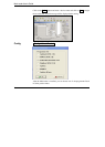
Optional Operation
X value Optional value of “don’t care”
Vcc Test Vcc value on Vcc pin
Delay Test period of each vector in mill-second
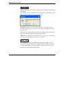
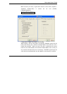
Test / IC Test
This operation tests TTL or CMOS logic devices according to the test patterns
stored in the test pattern library.