


MaxLoader User’s Guide
69
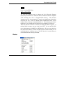
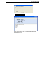
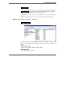
Device / Program
Program command will enable you to place new data from the memory buffer
into the target device. The BUSY GREEN led will be blinking during
programming. Make sure the device is correctly inserted into the ZIF socket and
the latch is down. Then check the buffer device address range before you start.
The values will default to the size of the device.
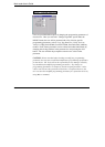
NOTE: <MOTOROLA MICROCONTROLLERS>
The window of windowed devices must be covered with an opaque label
during operation at all times.
NOTE: For all DEVICE/FUNCTION operations, the ERROR YELLOW LED,
located at the bottom of the ZIF socket is used to indicate the status of the
complete operation. It will turn on if an error has occurred; otherwise it will
remain off.
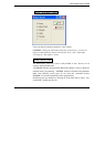
Memory device
The target device must be blank checked unless the part is electrically erasable.
Although most of EEPROMs and Flash Memory devices have the ERASE
function in the menu, some EEPROMs such as AT28CXXX or AT29CXXX
don’t have the ERASE function. Note that EEPROMs without the ERASE
function are automatically erased before programming.
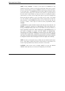
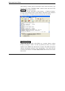
Programmable Logic Device operation
After programming is complete, verification should be performed according to
the semiconductor manufacturer's specifications. In order to test vectors, a
vector test should be performed (See vector test under the TEST menu). Finally,
the part may be secured so that its content can no longer be examined or
modified. The security function will not execute if the device fails to verify or
pass the vector test properly.
28C256, 28C010, etc.