


Refer to ″Specifications″ in the Enterprise Server S80 p Series 680 Model S85
Service Guide, order number SA38-0560, for more planning information.
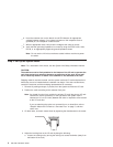
Step 4. Check Customer Outlets
Note: For a translation of this notice, see the
System Unit Safety Information
manual,
order number SA23-2652.
CAUTION:
Do not touch the receptacle or the receptacle faceplate with anything other than
your test probes before you have met the requirements in Step 8 below.
__ 1. Have the customer locate and turn off the branch circuit CB (circuit breaker).
Attach tag S229-0237, which reads “Do Not Operate.”
Note: All measurements are made with the receptacle faceplate in the normal
installed position.
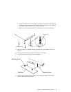
__ 2. Some receptacles are enclosed in metal housings. On receptacles of this type,
perform the following steps:
a. Check for less than 1 volt from the receptacle case to any grounded metal
structure in the building, such as a raised-floor metal structure, water pipe,
building steel, or similar structure.
b. Check for less than 1 volt from receptacle ground pin to a grounded point in
the building.
Note: If the receptacle case or faceplate is painted, be sure the probe tip
penetrates the paint and makes good electrical contact with the metal.
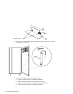
__ 3. Check the resistance from the ground pin of the receptacle to the receptacle
case. Check resistance from the ground pin to building ground. The reading
should be less than 1.0 ohm, which indicates the presence of a continuous
grounding conductor.
__ 4. If any of the three checks made in substeps 2 and 3 are not correct, ask the
customer to remove the power from the branch circuit and make the wiring
corrections; then check the receptacle again.
Note: Do not use the digital multimeter to measure grounding resistance.
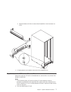
__ 5. Check for infinite resistance between the phase pins. This is a check for a wiring
short.
Note: For a translation of this notice, see the
System Unit Safety Information
manual, order number SA23-2652.
CAUTION:
If the reading is other than infinity, do not proceed! Have the customer
make necessary wiring corrections before continuing. Do not turn on the
branch circuit CB until all the above steps are satisfactorily completed.
Chapter 1. System Installation Procedure 3