


__ 6. Have the customer turn on the branch circuit CB. Measure for appropriate
voltages between phases. If no voltage is present on the receptacle case or
grounded pin, the receptacle is safe to touch.
__ 7. With an appropriate meter, verify that the voltage at the outlet is correct.
__ 8. Verify that the grounding impedance is correct by using the ECOS 1020, 1023,
B7106, or an appropriately approved ground impedance tester.
Note: Do
not
use the 120-volt convenience outlets inside a machine to power
the tester.
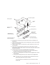
Step 5. Set Up the System Racks
Note: For a translation of this notice, see the
System Unit Safety Information
manual.
CAUTION:
The stabilizer must be firmly attached to the bottom of the I/O rack to prevent the
rack from turning over when the drawers are pulled out of the rack. Do not pull
out or install any drawer or feature if the stabilizer is not attached to the rack.
Shipping material must be removed, and the system rack and I/O rack and place them
where they are to be installed before installation can begin. If this has not been done,
consult the customer and the marketing representative as necessary.
1. Remove all packing and tape, if present, from the system rack and the I/O rack.
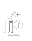
2. Position the racks according to the customer floor plan.
Note: As viewed from the front, position the primary I/O rack (the primary I/O rack
contains the service processor) on the right side of the system rack. A
clearance of 10 cm (4 inches) between the racks is required to allow access
to the I/O rack door.
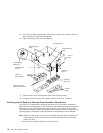
If you are attaching the racks to a concrete floor or a raised floor, refer to
“Step 6A. Attach the I/O Rack to a Concrete Floor” on page 7, and then
return here.
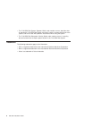
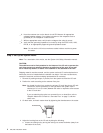
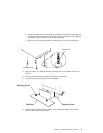
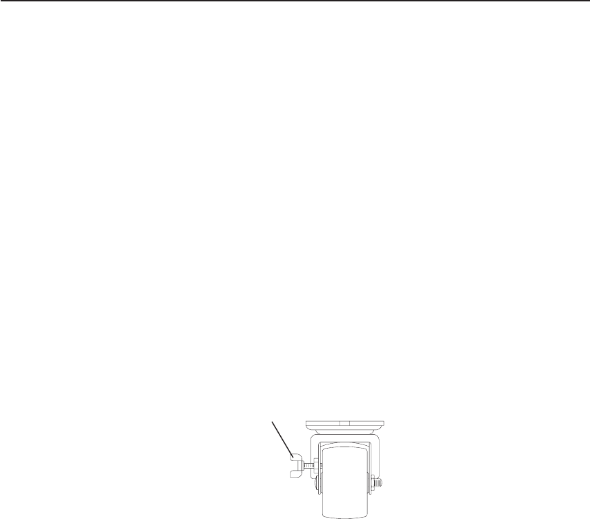
3. On both racks, lock each caster wheel by tightening the thumbscrew on the caster.
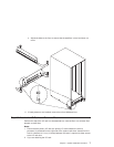
4. Adjust the leveling feet on the I/O rack by doing the following:
a. Loosen the locking nut by turning the locking nut counter-clockwise (away from
the bottom of the rack).
Thumbscrew
4 S80, S85 Installation Guide