


Notes:
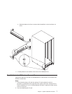
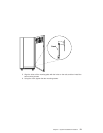
1. Ensure that the primary I/O rack (the primary I/O rack contains the service
processor) is positioned on the right side of the system rack when viewed from the
front. A clearance of 10 cm (4 inches) between the racks is required to allow access
to the I/O rack door.
2. If you are attaching the system rack:
v To a concrete floor, continue with “Attaching the System Rack to a Concrete
Floor”.
v To a concrete floor below a raised floor, go to “Attaching the System Rack to a
Concrete Floor Beneath a Raised Floor” on page 16.
If you are not attaching the system rack to a concrete floor, continue with “Step 7.
Attach the Front Electrical Outlet” on page 18.
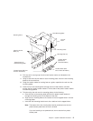
Attaching the System Rack to a Concrete Floor
The customer is responsible for attaching the rack-mounting plates to the concrete floor.
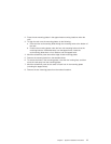
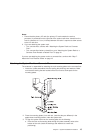
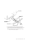
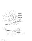
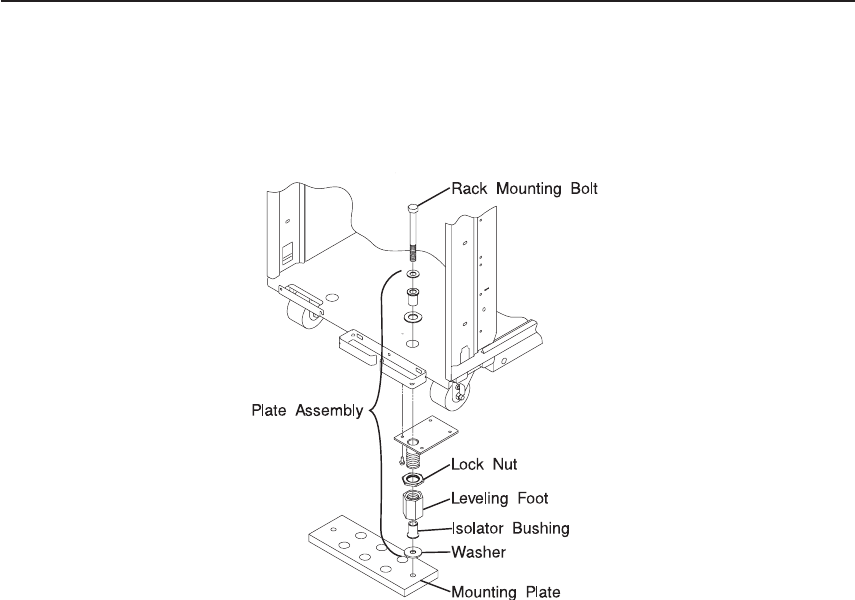
1. Install the 4 plate assemblies with the leveling feet, bushings and washers. Make
sure that the leveling feet are backed off the floor level to allow space for the
mounting plates.
2. Place the mounting plates, front and rear, (note that they are different) in the
approximate mounting position under the system rack.
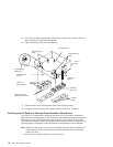
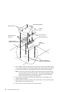
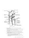
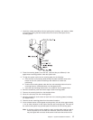
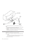
3. To align the system rack over the mounting plate, do the following:
a. Place the four rack-mounting bolts through the plate assembly holes at the
bottom of the rack (install the bushings and washers to ensure bolt
positioning).
Chapter 1. System Installation Procedure 15