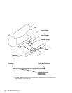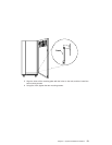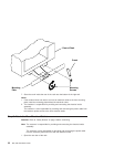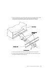
Step 11. Connect the Operator Panel Cable and the JTAG Cable Between the
Racks
Using the cables provided, connect the cables between the system rack and the
primary I/O drawer. Refer to “Appendix D. Cabling the System Rack and I/O Rack” on
page 47 for connector locations for these cables.
Step 12. Connect RIO and SPCN Cables Between the Racks
Using the cables provided, connect the RIO and SPCN cables between the system rack
and the I/O drawers. Refer to “Appendix D. Cabling the System Rack and I/O Rack” on
page 47 for valid cabling configurations.
Step 13. Set Up Attached Devices
Note: During the setup of each device, connect only the device end of the signal cable.
Do not
connect the device signal cables to the I/O rack now.
Do the setup procedures in the documentation for each device being attached to
the I/O rack; then return to “Step 14. Update the Device Records” on page 29.
Connect the ASCII terminal to serial port S1. Connect the keyboard, mouse, and
graphics display (if available). Refer to “I/O Drawer Locations” on page 50 for the
locations of the connectors.
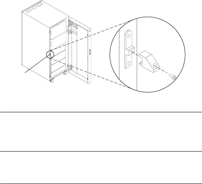
Door Guide
28 S80, S85 Installation Guide


