


v To a concrete floor, continue with “Attaching the I/O Rack to a Concrete Floor”.
v To a concrete floor below a raised floor, go to “Attaching the I/O Rack to a
Concrete Floor Beneath a Raised Floor” on page 10.
If you are not attaching the I/O rack to a concrete floor, continue with “Step 7. Attach
the Front Electrical Outlet” on page 18.
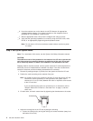
Attaching the I/O Rack to a Concrete Floor
The customer is responsible for attaching the rack-mounting plates to the concrete floor.
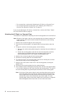
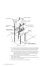
Note: Because of the length of the four rack-mounting bolts, the drawer located in the
bottom position of the rack
must
be removed to install the four rack-mounting
bolts to the floor.
1. Mark the floor around the edge of each leveling foot.
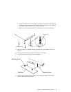
2. Place the two mounting plates in the approximate mounting locations under the
rack.
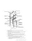
3. To align the rack over the mounting plates, do the following:
a. Place the four rack-mounting bolts through the mounting holes at the bottom of
the rack.
b. Position the mounting plates under the four rack-mounting bolts so that the
mounting bolts are centered directly over the tapped holes. Insert the
rack-mounting bolts three or four rotations into the tapped holes.
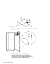
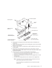
4. Mark the floor around the edge of both mounting plates.
5. Remove the mounting bolts from the threaded holes.
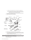
6. To access the holes in the mounting plates, raise the four leveling feet, and then
move the rack away from the mounting plates.
7. Mark the floor at the center of each hole in the mounting plates (including the
tapped holes).
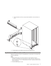
8. Remove the two mounting plates from the marked locations.
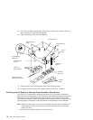
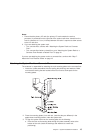
9. At the marked location of the tapped mounting holes, drill two holes approximately
1 inch to allow clearance for the ends of the two rack-mounting bolts. The ends of
the rack-mounting bolts may protrude past the thickness of the mounting plate.
Note: A minimum of three anchor bolts for each mounting plate must be used to
mount the plates to the concrete floor. Because some of the drilled holes
may be aligned with concrete reinforcement rods below the surface of the
concrete floor, some of the drilled holes may not be usable. For each
mounting plate, select at least three usable holes, two that are on opposite
sides and opposite ends of each other, and one hole at the center.
8 S80, S85 Installation Guide