


Thermal/Mechanical Reference Design
22 Quad-Core Intel® Xeon® Processor 5400 Series TMDG
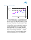
2.2.4.2 Thermal Monitor for Multiple Core Products
The thermal management for multiple core products has only one T
CONTROL
value per
processor. The T
CONTROL
for processor 0 and T
CONTROL
for processor 1 are independent
from each other. If the DTS temperature from any domain within the processor is
greater than or equal to T
CONTROL
, the processor case temperature must remain at or
below the temperature as specified by the thermal profile. See Section 2.2.6 for
information on T
CONTROL
. The PECI signal is available through CPU pin (G5) on each
LGA771 socket for the Quad-Core Intel® Xeon® Processor 5400 Series. Through this
pin, the two domains provide the current hottest value received from all the
temperature sensors, to an external PECI device such as a thermal management
system.
2.2.4.3 PROCHOT#, THERMTRIP#, and FORCEPR#
The PROCHOT# and THERMTRIP# outputs will be shared by all cores on a processor.
The first core to reach TCC activation will assert PROCHOT#. A single FORCEPR# input
will be shared by every core. Tab le 2-2 provides an overview of input and output
conditions for the Quad-Core Intel® Xeon® Processor 5400 Series thermal
management features.
2.2.4.4 Heatpipe Orientation for Multiple Core Processors
Thermal management of multiple core processors can be achieved without the use of
heatpipe heatsinks, as demonstrated by the Intel Reference Thermal Solution discussed
in Section 2.5.
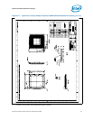
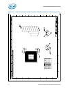
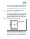
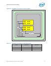
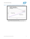
To assist customers interested in designing heatpipe heatsinks, processor core
locations have been provided. In some cases, this may influence the designer’s
selection of heatpipe orientation. For this purpose, the core geometric center locations,
as illustrated in Figure 2-6, are provided in Tab le 2 -3. Dimensions originate from the
vertical edge of the IHS nearest to the pin 1 fiducial as shown in Figure 2-6.
Table 2-2. Input and Output Conditions for the Quad-Core Intel® Xeon® Processor 5400
Series Thermal Management Features
Item Processor Input Processor Output
TM1/TM2
DTS
Core X > TCC Activation Temperature
All Cores TCC Activation
PROCHOT#
DTS
Core X > TCC Activation Temperature
PROCHOT# Asserted
THERMTRIP#
DTS
Core X > THERMTRIP # Assertion
Tem perat ure
THERMTRIP# Asserted,
all cores shut down
FORCEPR#
FORCEPR# Asserted All Cores TCC Activation
Note:
1. X=1,2,3,4; represents any one of the core1, core2, core3 and core4 in the Quad-Core Intel® Xeon® Processor 5400
Series.
2. For more information on PROCHOT#, THERMTRIP#, and FORCEPR# see the Quad-Core Intel® Xeon® Processor 5400
Series Datasheet.