


Heatsink Clip Load Methodology
86 Quad-Core Intel® Xeon® Processor 5400 Series TMDG
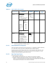
C.2.2 Typical Test Equipment
For the heatsink clip load measurement, use equivalent test equipment to the one
listed Ta bl e C-1.
Notes:
1. Select load range depending on expected load level. It is usually better, whenever possible, to operate in
the high end of the load cell capability. Check with your load cell vendor for further information.
2. Since the load cells are calibrated in terms of mV/V, a data logger or scanner is required to supply 5 volts
DC excitation and read the mV response. An automated model will take the sensitivity calibration of the
load cells and convert the mV output into pounds.
3. With the test equipment listed above, it is possible to automate data recording and control with a 6101-PCI
card (GPIB) added to the scanner, allowing it to be connected to a PC running LabVIEW* or Vishay's
StrainSmart* software.
4. IMPORTANT: In addition to just a zeroing of the force reading at no applied load, it is important to
calibrate the load cells against known loads. Load cells tend to drift. Contact your load cell vendor for
calibration tools and procedure information.
5. When measuring loads under thermal stress (bake for example), load cell thermal capability must be
checked, and the test setup must integrate any hardware used along with the load cell. For example, the
Model 13 load cells are temperature compensated up to 71 °C, as long as the compensation package
(spliced into the load cell's wiring) is also placed in the temperature chamber. The load cells can handle up
to 121 °C (operating), but their uncertainty increases according to 0.02% rdg/°F.
C.2.3 Test Procedure Examples
The following sections give two examples of load measurement. However, this is not
meant to be used in mechanical shock and vibration testing.
Any mechanical device used along with the heatsink attach mechanism will need to be
included in the test setup (i.e., back plate, attach to chassis, etc.).
Prior to any test, make sure that the load cell has been calibrated against known loads,
following load cell vendor’s instructions.
C.2.4 Time-Zero, Room Temperature Preload Measurement
1. Pre-assemble mechanical components on the board as needed prior to mounting
the motherboard on an appropriate support fixture that replicate the board attach
to a target chassis.
For example: If the attach mechanism includes fixtures on the back side of the
board, those must be included, as the goal of the test is to measure the load
provided by the actual heatsink mechanism.
2. Install the test vehicle in the socket.
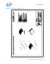
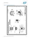
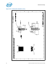
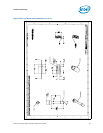
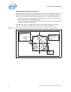
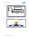
3. Assemble the heatsink reworked with the load cells to motherboard as shown for
the Quad-Core Intel® Xeon® Processor 5400 Series CEK-reference heatsink
example in Figure C-3, and actuate attach mechanism.
4. Collect continuous load cell data at 1 Hz for the duration of the test. A minimum
time to allow the load cell to settle is generally specified by the load cell vendors
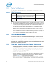
Table C-1. Typical Test Equipment
Item Description Part Number (Model)
Load cell
Notes: 1, 5
Honeywell*-Sensotec* Model 13 subminiature load cells,
compression only
Select a load range depending on load level being tested.
www.sensotec.com
AL322BL
Data Logger
(or scanner)
Notes: 2, 3, 4
Vishay* Measurements Group Model 6100 scanner with a
6010A strain card (one card required per channel).
Model 6100