


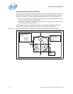


Heatsink Clip Load Methodology
84 Quad-Core Intel® Xeon® Processor 5400 Series TMDG
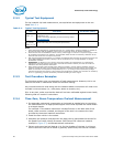
Alternate Heatsink Sample Preparation
As just mentioned, making sure that the load cells have minimum protrusion out of the
heatsink base is paramount to meaningful results. An alternate method to make sure
that the test setup will measure loads representative of the non-modified design is:
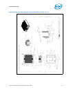
• Machine the pocket in the heatsink base to a depth such that the tips of the load
cells are just flush with the heatsink base.
• Then machine back the heatsink base by around 0.25 mm [0.01”], so that the load
cell tips protrude beyond the base.
Proceeding this way, the original stack height of the heatsink assembly should be
preserved. This should not affect the stiffness of the heatsink significantly.
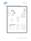
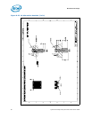
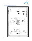
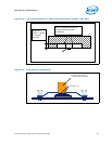
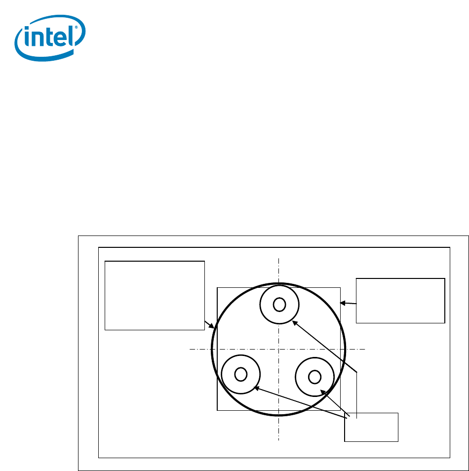
Figure C-1. Load Cell Installation in Machined Heatsink Base Pocket - Bottom View
Package IHS
Outline (Top
Surface)
Heatsink Base
Pocket
Diameter ~
29 mm
[~1.15”]
Load
Cells
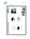
Package IHS
Outline (Top
Surface)
Heatsink Base
Pocket
Diameter ~
29 mm
[~1.15”]
Load
Cells