Power Management
32 Datasheet
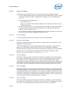
4.1.5 G, S, and C State Combinations
4.2 Processor Core / Package Power Management
While executing code, Enhanced Intel SpeedStep
®
Technology optimizes the processor
frequency and core voltage based on workload. Each frequency and voltage operating
point is defined by ACPI as a P-State. When the processor is not executing code, it is
idle. A low-power idle state is defined by ACPI as a C-state. In general, lower power C-
States have longer entry and exit latencies.
4.2.1 Enhanced Intel
®
SpeedStep
®
Technology
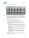
The following are the key features of Enhanced Intel SpeedStep
®
Technology:
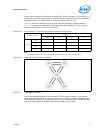
• Multiple frequency and voltage points for optimal performance and power
efficiency. These operating points are known as P-States.
• Frequency selection is software controlled by writing to processor MSRs. The
voltage is optimized based on temperature, leakage, power delivery loadline, and
dynamic capacitance.
— If the target frequency is higher than the current frequency, V
CC
is ramped up
to an optimized voltage. This voltage is signaled by the SVID Bus to the voltage
regulator. Once the voltage is established, the PLL locks on to the target
frequency.
— If the target frequency is lower than the current frequency, the PLL locks to the
target frequency, then transitions to a lower voltage by signaling the target
voltage on the SVID Bus.
— All active processor cores share the same frequency and voltage. In a multi-
core processor, the highest frequency P-state requested amongst all active
cores is selected.
— Software-requested transitions are accepted at any time. The processor has a
new capability from the previous processor generation; it can preempt the
previous transition and complete the new request without waiting for this
request to complete.
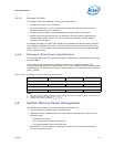
• The processor controls voltage ramp rates internally to ensure glitch-free
transitions.
• Because there is low transition latency between P-states, a significant number of
transitions per second are possible.
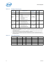
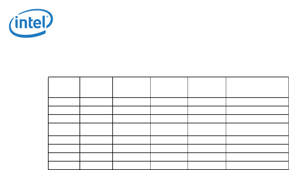
Table 4-6. G, S and C State Combinations
Global (G)
State
Sleep
(S) State
Processor
Core
(C) State
Processor
State
System
Clocks
Description
G0 S0 C0 Full On On Full On
G0 S0 C1/C1E Auto-Halt On Auto-Halt
G0 S0 C3 Deep Sleep On Deep Sleep
G0 S0 C6/C7
Deep Power
Down
On
Deep Power Down
G1 S3 Power off — Off, except RTC Suspend to RAM
G1 S4 Power off — Off, except RTC Suspend to Disk
G2 S5 Power off — Off, except RTC Soft Off
G3 N/A Power off — Power off Hard off


