Electrical Specifications
70 Datasheet
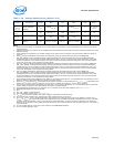
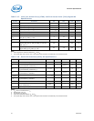
Note:
1. These signals are measured between V
IL
and V
IH
.
2. The signal edge rate must be met or the signal must transition monotonically to the asserted state.
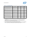
Notes:
1. V
TT
refers to instantaneous V
TT
.
2. Measured at 0.31*V
TT
3. Vin between 0V and V
TT
4. These are measured between V
IL
and V
IH
.
5. The signal edge rate must be met or the signal must transition monotonically to the asserted state.
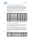
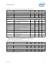
Table 7-17. Joint Test Action Group (JTAG) and Test Access Point (TAP) Signals DC
Specifications
Symbol Parameter Min Max Units Notes
V
IL
Input Low Voltage — 0.3*V
TT
V
V
IH
Input High Voltage 0.7*V
TT
—V
V
IL
Input Low Voltage: PREQ_N — 0.4*V
TT
V
V
IH
Input High Voltage: PREQ_N 0.8*V
TT
—V
V
OL
Output Low Voltage — 0.2*V
TT
V
V
Hysteresis
Hysteresis 0.1*V
TT
—V
R
ON
Buffer On Resistance
BPM_N[7:0], PRDY_N, TDO
414
I
IL
Input Leakage Current 50 200 A
Input Edge Rate
Signals: BPM_N[7:0], EAR_N, PREQ_N, TCK, TDI,
TMS, TRST_N
0.05 — V/ns 1, 2
Output Edge Rate (50 ohm to V
TT
)
Signal: BPM_N[7:0], PRDY_N, TDO
0.2 1.5 V/ns 1
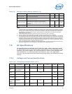
Table 7-18. Serial VID Interface (SVID) DC Specifications
Symbol Parameter Min Typ Max Units Notes
V
TT
Processor I/O Voltage VTT – 3% 1.0 VTT + 3% V
V
IL
Input Low Voltage
Signals SVIDDATA, SVIDALERT_N
— — 0.4*V
TT
V1
V
IH
Input High Voltage
Signals SVIDDATA, SVIDALERT_N
0.7*V
TT
——V1
V
OL
Output Low Voltage
Signals SVIDCLK, SVIDDATA
— — 0.3*V
TT
V1
V
Hysteresis
Hysteresis 0.05*V
TT
——V1
R
ON
Buffer On Resistance
Signals SVIDCLK, SVIDDATA
4—14W2
I
IL
Input Leakage Current ±50 — ±200 A3
Input Edge Rate
Signal: SVIDALERT_N
0.05 — — V/ns 4, 5
Output Edge Rate (50 ohm to V
TT
) 0.20 — 1.5 V/ns 4


