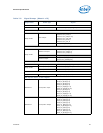
Datasheet 63
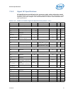
Electrical Specifications
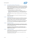
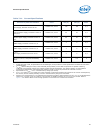
Notes:
1. Storage conditions are applicable to storage environments only. In this scenario, the processor must not
receive a clock, and no lands can be connected to a voltage bias. Storage within these limits will not affect
the long-term reliability of the device. For functional operation, refer to the processor case temperature
specifications in the appropriate processor Thermal Mechanical Specifications and Design Guide (see
Related Documents section).
2. These ratings apply to the Intel component and do not include the tray or packaging.
3. Failure to adhere to this specification can affect the long-term reliability of the processor.
4. Non-operating storage limits post board attach: Storage condition limits for the component once attached
to the application board are not specified. Intel does not conduct component level certification assessments
post board attach given the multitude of attach methods, socket types and board types used by customers.
Provided as general guidance only, Intel board products are specified and certified to meet the following
temperature and humidity limits (Non-Operating Temperature Limit: -40 °C to 70 °C and Humidity: 50% to
90%, non condensing with a maximum wet bulb of 28 °C).
5. Device storage temperature qualification methods follow JEDEC* High and Low Temperature Storage Life
Standards: JESD22-A119 (low temperature) and JESD22-A103 (high temperature).
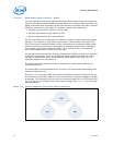
7.5 DC Specifications
DC specifications are defined at the processor pads, unless otherwise noted.
DC specifications are only valid while meeting specifications for case temperature, clock
frequency, and input voltages. Care should be taken to read all notes associated with
each specification. For case temperature specifications, refer to the appropriate
processor Thermal Mechanical Specifications and Design Guide (see Related Documents
section).
7.5.1 Voltage and Current Specifications
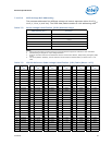
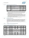
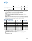
T
short term storage
The ambient storage temperature (in shipping media)
for a short period of time.
-20 85 °C
RH
sustained storage
The maximum device storage relative humidity for a
sustained period of time.
60% @ 24 °C
Time
sustained storage
A prolonged or extended period of time; typically
associated with sustained storage conditions
Unopened bag, includes 6 months storage time by
customer.
0 30 months
Time
short term storage
A short period of time (in shipping media).
0 72 hours
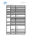
Table 7-9. Storage Condition Ratings (Sheet 2 of 2)
Symbol Parameter Min Max Unit
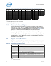
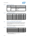
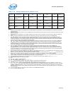
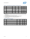
Table 7-10. Voltage Specifications (Sheet 1 of 2)
Symbol Parameter
Voltage
Plane
Min Typ Max Unit Notes
1
V
CC
VID
V
CC
VID Range
— 0.6 — 1.35 V 2, 3
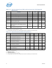
V
Retention
VID
Retention Voltage
VID in package C3
and C6 states
— — 0.65 — V 2, 3
V
CC
LL
V
CC
Loadline Slope
V
CC
0.8 m
3, 4, 7, 8,
11, 13, 18
V
CC
TOB
V
CC
Tolerance Band
V
CC
15 mV
3, 4, 7, 8,
11, 13, 18
V
CC
Ripple
V
CC
Ripple
Vcc 5 mV
3, 4, 7, 8,
11, 13, 18
V
VID_STEP
(Vcc, Vsa,
Vccd)
VID step size during
a transition
— — 5.0 — mV 10
V
CCPLL
PLL Voltage
V
CCPLL
0.955*V
CCPLL_TYP
1.7 1.045*V
CCPLL_TYP
V
11, 12, 13,
17


