


6.14 Processor Internal Pull-Up / Pull-Down Terminations................................................ 85
7.0 Electrical Specifications.............................................................................................. 86
7.1 Integrated Voltage Regulator..................................................................................86
7.2 Power and Ground Lands ...................................................................................... 86
7.3 V
CC
Voltage Identification (VID).............................................................................. 86
7.4 Reserved or Unused Signals................................................................................... 91
7.5 Signal Groups.......................................................................................................91
7.6 Test Access Port (TAP) Connection.......................................................................... 93
7.7 DC Specifications.................................................................................................93
7.8 Voltage and Current Specifications.......................................................................... 94
7.8.1 PECI DC Characteristics............................................................................. 99
7.8.2 Input Device Hysteresis........................................................................... 100
8.0 Package Mechanical Specifications........................................................................... 101
8.1 Processor Component Keep-Out Zone.................................................................... 101
8.2 Package Loading Specifications............................................................................. 101
8.3 Package Handling Guidelines................................................................................ 102
8.4 Package Insertion Specifications............................................................................102
8.5 Processor Mass Specification.................................................................................102
8.6 Processor Materials............................................................................................. 102
8.7 Processor Markings............................................................................................. 103
8.8 Processor Land Coordinates..................................................................................103
8.9 Processor Storage Specifications........................................................................... 104
9.0 Processor Ball and Signal Information...................................................................... 106
Figures
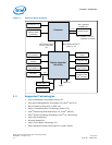
1 Platform Block Diagram ...........................................................................................10
2 Intel
®
Flex Memory Technology Operations.................................................................20
3 PCI Express* Related Register Structures in the Processor............................................ 24
4 PCI Express* Typical Operation 16 Lanes Mapping....................................................... 25
5 Processor Graphics Controller Unit Block Diagram........................................................ 28
6 Processor Display Architecture...................................................................................31
7 DisplayPort* Overview............................................................................................. 32
8 HDMI* Overview..................................................................................................... 33
9 Example for PECI Host-Clients Connection.................................................................. 37
10 Device to Domain Mapping Structures........................................................................ 41
11 Processor Power States............................................................................................ 48
12 Idle Power Management Breakdown of the Processor Cores ..........................................51
13 Thread and Core C-State Entry and Exit......................................................................52
14 Package C-State Entry and Exit................................................................................. 56
15 Thermal Test Vehicle (TTV) Case Temperature (T
CASE
) Measurement Location..................64
16 Digital Thermal Sensor (DTS) 1.1 Definition Points.......................................................65
17 Digital Thermal Sensor (DTS) Thermal Profile Definition................................................67
18 Package Power Control.............................................................................................75
19 Input Device Hysteresis..........................................................................................100
20 Processor Package Assembly Sketch.........................................................................101
21 Processor Top-Side Markings...................................................................................103
22 Processor Package Land Coordinates........................................................................ 104
Contents—Processor
Intel
®
Xeon
®
Processor E3-1200 v3 Product Family
June 2013 Datasheet – Volume 1 of 2
Order No.: 328907-001 5