


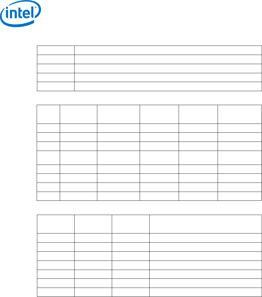
Table 13. Direct Media Interface (DMI) States
State Description
L0 Full on – Active transfer state.
L0s First Active Power Management low power state – Low exit latency.
L1 Lowest Active Power Management – Longer exit latency.
L3 Lowest power state (power-off) – Longest exit latency.
Table 14. G, S, and C Interface State Combinations
Global
(G)
State
Sleep (S)
State
Processor
Package (C)
State
Processor
State
System Clocks Description
G0 S0 C0 Full On On Full On
G0 S0 C1/C1E Auto-Halt On Auto-Halt
G0 S0 C3 Deep Sleep On Deep Sleep
G0 S0 C6/C7
Deep Power-
down
On Deep Power-down
G1 S3 Power off Off, except RTC Suspend to RAM
G1 S4 Power off Off, except RTC Suspend to Disk
G2 S5 Power off Off, except RTC Soft Off
G3 NA Power off Power off Hard off
Table 15. D, S, and C Interface State Combination
Graphics
Adapter (D)
State
Sleep (S)
State
Package (C)
State
Description
D0 S0 C0 Full On, Displaying.
D0 S0 C1/C1E Auto-Halt, Displaying.
D0 S0 C3 Deep sleep, Displaying.
D0 S0 C6/C7 Deep Power-down, Displaying.
D3 S0 Any Not displaying.
D3 S3 N/A Not displaying, Graphics Core is powered off.
D3 S4 N/A Not displaying, suspend to disk.
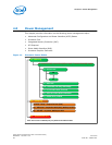
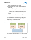
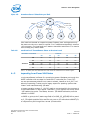
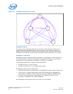
4.2 Processor Core Power Management
While executing code, Enhanced Intel SpeedStep
®
Technology optimizes the
processor’s frequency and core voltage based on workload. Each frequency and
voltage operating point is defined by ACPI as a P-state. When the processor is not
executing code, it is idle. A low-power idle state is defined by ACPI as a C-state. In
general, deeper power C-states have longer entry and exit latencies.
4.2.1
Enhanced Intel
®
SpeedStep
®
Technology Key Features
The following are the key features of Enhanced Intel SpeedStep Technology:
Processor—Power Management
Intel
®
Xeon
®
Processor E3-1200 v3 Product Family
Datasheet – Volume 1 of 2 June 2013
50 Order No.: 328907-001