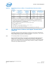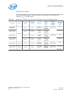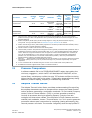
Processor PCG
2
Package
TDP
3
Platform
TDP
4
Heatsink
5
T
LA
,
Airflow,
RPM,
Ѱ
CA
6
Maximum
T
CASE
Thermal
Profile
7
T
CASE-MAX
@
Platform
TDP
8
2C/GT2 35 W
1
2013A
35 W 35 W
Active Short
(DHA-D)
45.4 °C,
3000 RPM,
0.597 °C/W
y = 0.51 *
Power + 48.5
66.3 °C
4C/GT0 25 W
1
25 W 25 W
ATCA
Reference
Heatsink
9
67 °C,
10 CFM,
0.565 °C/W
y = 0.48 *
Power + 69.1
81.1 °C
2C/GT0 16 W
1
16 W 16 W
ATCA
Reference
Heatsink
9
67 °C,
10 CFM,
0.565 °C/W
y = 0.48 *
Power + 68.2
75.8 °C
Notes: 1. TDP shown here, 95 W for example, represents the maximum expected platform TDP in the next generation
platform for this type of SKU. This placeholder value is provided as a guideline for hardware design for the next
generation platform.
2. Platform Compatibility Guide (PCG) provides a design target for meeting all planned processor frequency
requirements. For more information, refer to Voltage and Current Specifications on page 94.
3. Package Thermal Design Power (TDP) is for the Intel
®
Xeon
®
processor E3-1200 v3 Product Family.
4. Platform Thermal Design Power (TDP) includes projections for the refresh processor that follow the Intel
®
Xeon
®
processor E3-1200 v3 Product Family in this platform.
5. Thermal Solution information can be found in the following table.
6. These boundary conditions and performance targets are used to generate processor thermal specifications and to
provide guidance for heatsink design. Values are for the heatsink shown in the adjacent column are calculated at sea
level, and are expected to meet the Thermal Profile at TDP. T
LA
is the local ambient temperature of the heatsink
inlet air. Airflow is through the heatsink fins with zero bypass for a passive heatsink. RPM is fan revolutions per
minute for an active heatsink. Ѱ
CA
is the maximum target (mean + 3 sigma) for the thermal characterization
parameter. For more information on the thermal characterization parameter, refer to the processor Thermal
Mechanical Design Guidelines (see Related Documents section).
7. Maximum T
CASE
Thermal Profile is the specification that must be complied to. Any Attempt to operate the processor
outside these operating limits may result in permanent damage to the processor and potentially other system
components.
8. T
CASE-MAX
at Platform TDP is calculated using the maximum T
CASE
Thermal Profile and the platform TDP.
9. ATCA Reference Heatsink supports Socket B and is not tooled for Socket H.
5.5 Processor Temperature
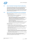
A software readable field in the TEMPERATURE_TARGET register that contains the
minimum temperature at which the TCC will be activated and PROCHOT# will be
asserted. The TCC activation temperature is calibrated on a part-by-part basis and
normal factory variation may result in the actual TCC activation temperature being
higher than the value listed in the register. TCC activation temperatures may change
based on processor stepping, frequency or manufacturing efficiencies.
5.6
Adaptive Thermal Monitor
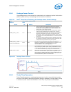
The Adaptive Thermal Monitor feature provides an enhanced method for controlling
the processor temperature when the processor silicon exceeds the Thermal Control
Circuit (TCC) activation temperature. Adaptive Thermal Monitor uses TCC activation to
reduce processor power using a combination of methods. The first method (Frequency
control, similar to Thermal Monitor 2 (TM2) in previous generation processors)
involves the processor reducing its operating frequency (using the core ratio
multiplier) and internal core voltage. This combination of lower frequency and core
voltage results in a reduction of the processor power consumption. The second
method (clock modulation, known as Thermal Monitor 1 or TM1 in previous generation
processors) reduces power consumption by modulating (starting and stopping) the
internal processor core clocks. The processor intelligently selects the appropriate TCC
Thermal Management—Processor
Intel
®
Xeon
®
Processor E3-1200 v3 Product Family
June 2013 Datasheet – Volume 1 of 2
Order No.: 328907-001 69


