


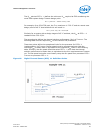

Table 18. Digital Thermal Sensor (DTS) 1.1 Thermal Solution Performance Above
T
CONTROL
Processor
TDP
Ψ
CA
at DTS =
T
CONTROL
1, 2
At System T
AMBIENT-
MAX
= 30 °C
Ψ
CA
at DTS = -1
At System
T
AMBIENT-MAX
= 40 °C
Ψ
CA
at DTS = -1
At System
T
AMBIENT-MAX
= 45 °C
Ψ
CA
at DTS = -1
At System T
AMBIENT-
MAX
= 50 °C
84 W 0.627 0.390 0.330 0.270
65 W 0.793 0.482 0.405 0.328
45 W 1.207 0.699 0.588 0.477
35 W 1.406 0.753 0.610 0.467
1. Ψ
CA
at "DTS = T
CONTROL
" is applicable to systems that have an internal T
RISE
(T
ROOM
temperature to
Processor cooling fan inlet) of less than 10 °C. In case the expected T
RISE
is greater than 10 °C, a
correction factor should be used as explained below. For each 1 °C T
RISE
above 10 °C, the correction
factor (CF) is defined as CF = 1.7 / (processor TDP)
2. Example: A chassis T
RISE
assumption is 12 °C for a 95 W TDP processor:
CF = 1.7 / 95 W = 0.018 /W
For T
RISE
> 10 °C
Ψ
CA
at T
CONTROL
= (Value provide in Column 2) – (T
RISE
– 10) * CF
Ψ
CA
= 0.627 – (12 – 10) * 0.018 = 0.591 °C/W
In this case, the fan speed should be set slightly higher, equivalent to Ψ
CA
= 0.591 °C/W
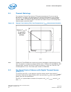
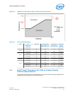
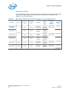
5.3 Fan Speed Control Scheme with Digital Thermal Sensor
(DTS) 2.0
To simplify processor thermal specification compliance, the processor calculates the
DTS Thermal Profile from T
CONTROL
Offset, TCC Activation Temperature, TDP, and the
Thermal Margin Slope provided in the following table.
Note: TCC Activation Offset is 0 for the processors.
Using the DTS Thermal Profile, the processor can calculate and report the Thermal
Margin, where a value less than 0 indicates that the processor needs additional
cooling, and a value greater than 0 indicates that the processor is sufficiently cooled.
Refer to the processor Thermal Mechanical Design Guidelines (TMDG) for additional
information (see Related Documents).
Processor—Thermal Management
Intel
®
Xeon
®
Processor E3-1200 v3 Product Family
Datasheet – Volume 1 of 2 June 2013
66 Order No.: 328907-001