


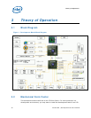
Theory of Operation
28 316704-001 / Development Kit User’s Manual
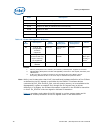
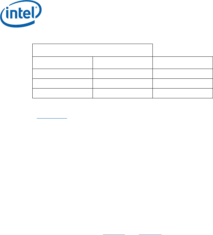
Table 7. BIOS Location Strapping Options
ICH8-M Signal
GNT#0 SPI_CS1# BIOS Location
0 1 SPI
1 0 PCI
1 1 LPC (Default)
Note: GNT#0 is configurable via jumper J8E2. Further details on its location can be found in
Section 4.3. SPI_CS1# is configurable via stuffing option R7U12. By default R7U12 is
not stuffed resulting in a SPI_CS1# strapping value of 1.
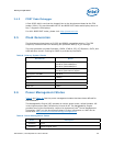
3.4.2.11 System Management Controller (SMC)/Keyboard Controller
The Hitachi* H8S/2104RV serves as both SMC and KBC for the development board.
The SMC/KBC controller supports two PS/2 ports, battery monitoring and charging,
EMA support, wake/runtime SCI events, and power sequencing control. The two PS/2
ports on the development board are for legacy keyboard and mouse. The keyboard
plugs into the bottom jack and the mouse plugs into the top jack at J1A1. Scan matrix
keyboards can be supported via an optional connector at J9E1.
3.4.2.12 Clocks
The development board uses a CK-505 clock synthesizer and DB800 clock buffer
compatible solution. The FSB frequency is determined from decoding the processor
BSEL[2:0] pin settings. This pin settings may be strapped using the jumpers at J1G2,
J1G5 and J1G8. Refer to Figure 7
and Table 15 for further information on these
jumpers.
3.4.2.13 Real Time Clock
An on-board battery at BT5H1 maintains power to the real time clock (RTC) when in a
mechanical off state. A CR2032 battery is installed on the development board.
Warning: Risk of explosion if the lithium battery is replaced by an incorrect type. Dispose of
used batteries according to the vendor's instructions.
3.4.2.14 Thermal Monitoring
The processor has a thermal diode for temperature monitoring. The SMC throttles the
processor if it becomes hot. If the temperature of the processor rises too high, the
SMC alternately blinks the CAPS lock and NUM lock LEDs on the development board,
and the development board shuts down.
A 3-pin fan header J3C1 is provided to support Tachometer output measurement for
GMCH. The development board supports PWM based speed control. As part of the
thermal measurement, the speed of the fan is varied based on the temperature
measurement.