


Hardware Reference
316704-001 / Development Kit User’s Manual 65
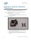
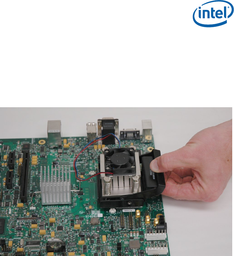
7. While keeping the activation arm compressed, place the heatsink over the pins
of the heatsink backplate. Lower the heatsink until the lugs have inserted into
the base of the heatsink. Slide the heatsink over the lugs on the backplate
pins so that the base is directly over the processor die and the pins on the
backplate have travelled the entire length of the channel in the heatsink base.
Slowly let go of the activation arm until the base of the heatsink makes
contact with the processor die. The heatsink base should be flat on top of the
processor die.
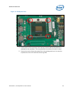
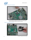
Figure 13. Installing the Heatsink
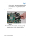
8. Plug the fan connector for the heatsink onto the CPU fan header (J2B3) on the
motherboard.
Note: The CPU fan header (J2B3) is a 3-pin connector. This is a change from the Mobile
Intel® 945GM Express Chipset Development Kit which has a 2-pin CPU fan header. As
a result, it is not possible to use the heatsink from the Intel® 945GM Express Chipset
Development Kit even though the heatsink and backplate are mechanically
compatible.