


Hardware Reference
42 316704-001 / Development Kit User’s Manual
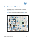
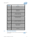
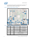
The unsupported jumpers must remain in their default position or the operation of the
development board is unpredictable. The development board is shipped with the
jumpers and switches shunted in the default locations.
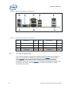
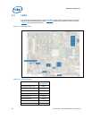
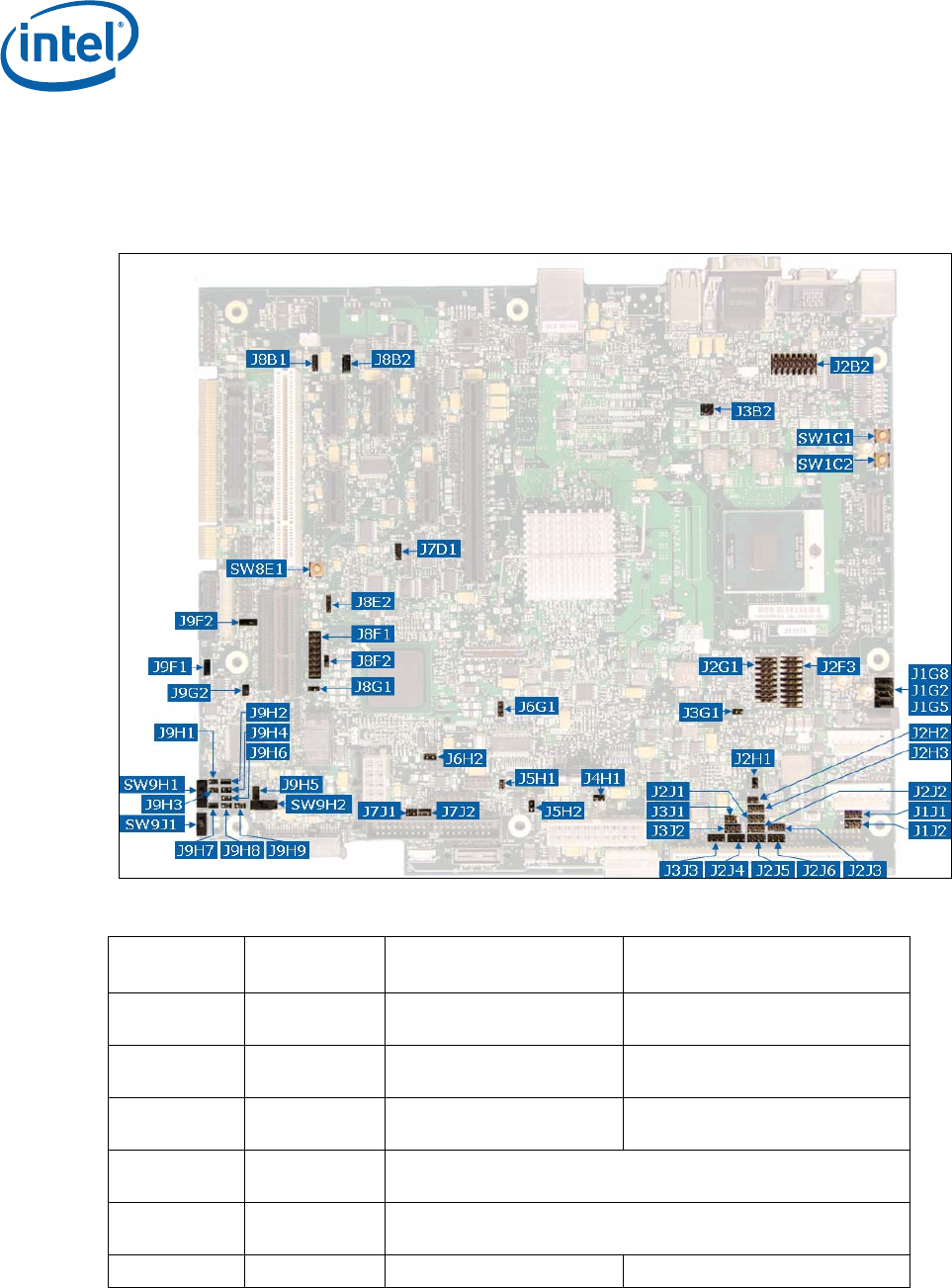
Figure 7. Configuration Jumper and Switch Locations
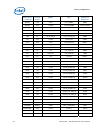
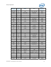
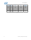
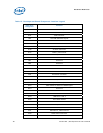
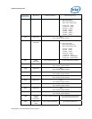
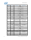
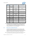
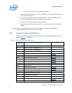
Table 15. Supported Configuration Jumper/Switch Settings
Reference
Designator
Function Default Setting Optional Setting
J1G2 BSEL0
1-2: Processor BSEL Select
2-3: Tied to logic high
Empty: Tied to logic low
J1G5 BSEL1
1-2: Processor BSEL Select
2-3: Tied to logic low
Empty: Tied to logic high
J1G8 BSEL2
1-2: Processor BSEL Select
2-3: Tied to logic low
Empty: Tied to logic high
J1J1 Reserved OUT
Do not alter jumper setting
J1J2 Reserved OUT
Do not alter jumper setting
J2B2 CPU VID Code OUT 15-16: Activate Override