


Hardware Reference
58 316704-001 / Development Kit User’s Manual
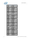
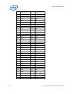
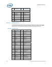
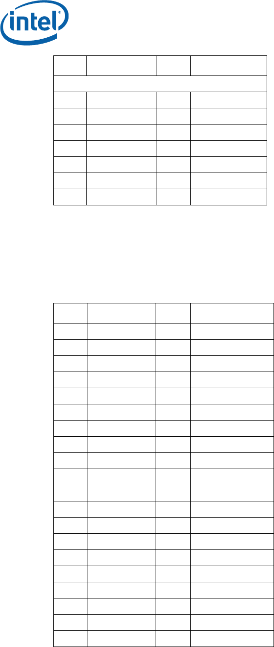
Pin Description Pin Description
Key
A12 GND B12 RSVD
A13 REFCLK+ B13 GND
A14 REFCLK- B14 LANE 0 (T+)
A15 GND B15 LANE 0 (T-)
A16 LANE 0 (R+) B16 GND
A17 LANE 0 (R-) B17 PRSNT2*
A18 GND B18 GND
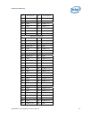
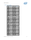
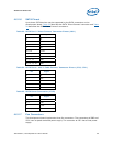
4.6.2.5 IDE Connector
The IDE interface can support up to two devices, a master and a slave. Ensure that
the jumpers on the devices are properly selected for the given configuration. Mobile
devices with an IDE interface will require an adapter to connect to this port.
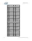
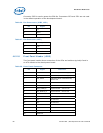
Table 22. IDE Connector
Pin Signal Pin Signal
1 Reset 2 Ground
3 Data 7 4 Data 8
5 Data 6 6 Data 9
7 Data 5 8 Data 10
9 Data 4 10 Data 11
11 Data 3 12 Data 12
13 Data 2 14 Data 13
15 Data 1 16 Data 14
17 Data 0 18 Data 15
19 Ground 20 Key
21 DDRQ 22 Ground
23 I/O Write 24 Ground
25 I/O Read 26 Ground
27 I/O HRDY 28 Cable Select
29 DDACK 30 Ground
31 IRQ 32 No Connect
33 Address 1 34 DMA66_Detect
35 Address 0 36 Address 2
37 Chip Select 1 38 Chip Select 3
39 Activity 40 Ground