Hardware Reference
40 316704-001 / Development Kit User’s Manual
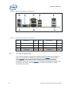
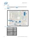
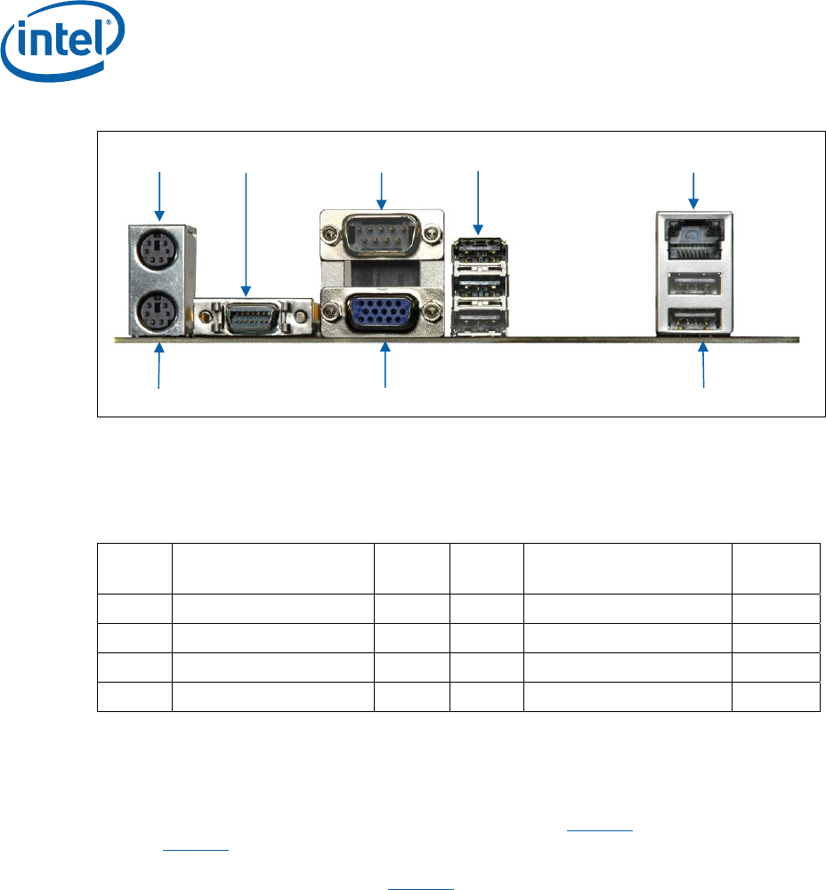
Figure 3. Back Panel Connector Locations
n o p q r
s t u
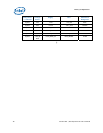
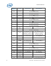
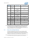
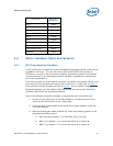
Table 14. Back Panel Connector Definitions
Item Description Ref
Des
Item Description Ref Des
1 PS/2 Mouse J1A1 5 RJ-45 LAN J5A1
2 TV-Out D-Connector J2A1 6 PS/2 Keyboard J1A1
3 Serial Port J2A2 7 VGA J2A2
4 3 USB Ports J3A1 8 2 USB Ports J5A1
4.2.1 TV-Out D-Connector
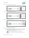
The TV-Out D-connector supplies the necessary signals to support the Composite, S-
Video, and Component TV standards. Component video (Figure 4
) and Composite
video (Figure 5
) is connected to the development board using D-connector to
Component Video cable (with three RCA receptacles at one end and D-mating
connector on other end). S-video (Figure 6
) is connected to development board using
D-connector to S-Video cable (with 4-pin DIN connector one end and D-mating
connector on other end).


