Theory of Operation
30 316704-001 / Development Kit User’s Manual
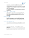
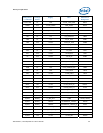
State Description
G0/S0/C3 Deep Sleep: DPSLP# signal active
G0/S0/C4 Deeper Sleep: DPRSLP# signal active
G1/S3 Suspend To RAM (all switched rails are turned off)
G1/S4 Suspend To Disk
G2/S5 Soft Off
G3 Mechanical Off
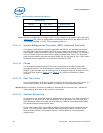
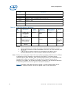
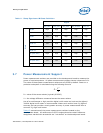
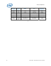
Table 10. Power Management M-States
M-
State
Description Main
System
Memory
Subsystem
1
Manageability
Subsystem
2
Clocks
M0 Full on. All
manageability
functions
supported
Powered Powered and
active
Powered Powered
M1 Manageability
functions that only
require memory
are supported
Off Powered - Self
refresh.
Powered Only
BCLK pair
to MCH is
active
3
M-off Manageability is
disabled
Off Off Off Off
NOTES:
1. Memory subsystem is the memory and memory-related power supplies to the MCH.
2. Manageability Subsystem includes manageability functions in the chipset, SPI flash, and
LAN devices.
3. In M1 the clock is powered, however only the BCLK pair to the MCH is active.
Everything besides the PLL in the clock chip is disabled and powered down.
Note: While in an M-state other than M-off, the traditional hardware definition of the S-State
as defined by the SLP signals is overridden by the ICH8M. This allows devices
controlled by SLP_S3# and SLP_S4#, such as system memory, to be available to the
Manageability system as needed. Even though the SLP signals may be driven
differently in M-States, the S-State information is retained in the ICH8M for transition
to M-off. S4_STATE# is the new signal to indicate S4 transition.
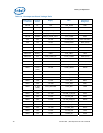
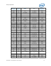
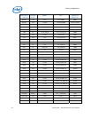
Table 11
provides a truth table of the SLP signals in various system states and M-
States. The ICH8M provides all of the SLP signals shown in the table below.


