


About This Manual
8 316704-001 / Development Kit User’s Manual
1.3 Glossary of Terms and Acronyms
Table 2 defines conventions and terminology used throughout this document.
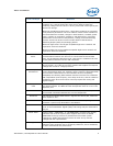
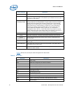
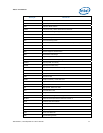
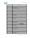
Table 2. Terms and Acronyms
Term/Acronym Definition
Aggressor A network that transmits a coupled signal to another network.
Anti-etch Any plane-split, void or cutout in a VCC or GND plane.
Assisted Gunning
Transceiver Logic+
The front-side bus uses a bus technology called AGTL+, or Assisted
Gunning Transceiver Logic. AGTL+ buffers are open-drain, and require
pull-up resistors to provide the high logic level and termination. AGTL+
output buffers differ from GTL+ buffers with the addition of an active
pMOS pull-up transistor to assist the pull-up resistors during the first clock
of a low-to-high voltage transition.
Asynchronous
GTL+
The processor does not utilize CMOS voltage levels on any signals that
connect to the processor. As a result, legacy input signals such as A20M#,
IGNNE#, INIT#, LINT0/INTR, LINT1/NMI, PWRGOOD, SMI#, SLP#, and
STPCLK# utilize GTL+ input buffers. Legacy output signals (FERR# and
IERR#) and non-AGTL+ signals (THERMTRIP# and PROCHOT#) also
utilize GTL+ output buffers. All of these signals follow the same DC
requirements as AGTL+ signals, however the outputs are not actively
driven high (during a logical 0 to 1 transition) by the processor (the major
difference between GTL+ and AGTL+). These signals do not have setup or
hold time specifications in relation to BCLK[1:0], and are therefore
referred to as “Asynchronous GTL+ Signals”. However, all of the
Asynchronous GTL+ signals are required to be asserted for at least two
BCLKs in order for the processor to recognize them.
Bus Agent A component or group of components that, when combined, represent a
single load on the AGTL+ bus.
Crosstalk The reception on a victim network of a signal imposed by aggressor
network(s) through inductive and capacitive coupling between the
networks.
Backward Crosstalk - Coupling that creates a signal in a victim network
that travels in the opposite direction as the aggressor’s signal.
Forward Crosstalk - Coupling that creates a signal in a victim network that
travels in the same direction as the aggressor’s signal.
Even Mode Crosstalk - Coupling from a signal or multiple aggressors when
all the aggressors switch in the same direction that the victim is switching.
Odd Mode Crosstalk - Coupling from a signal or multiple aggressors when
all the aggressors switch in the opposite direction that the victim is
switching.
Flight Time Flight time is a term in the timing equation that includes the signal
propagation delay, any effects the system has on the T
CO
(time from
clock-in to data-out) of the driver, plus any adjustments to the signal at
the receiver needed to ensure the setup time of the receiver. More
precisely, flight time is defined as:
The time difference between a signal at the input pin of a receiving agent
crossing the switching voltage (adjusted to meet the receiver