


Theory of Operation
316704-001 / Development Kit User’s Manual 31
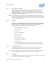
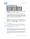
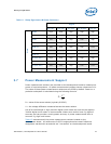
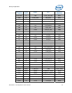
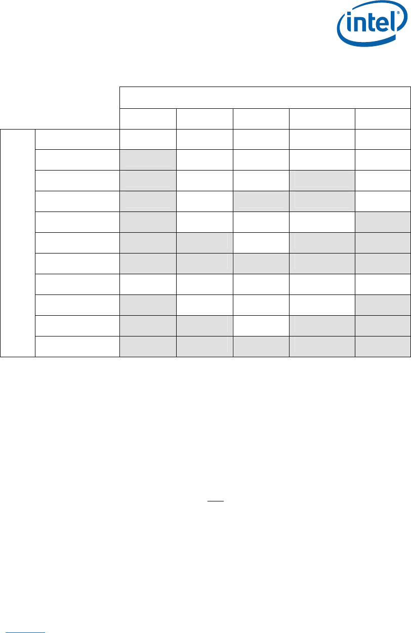
Table 11. Sleep Signals and M-State Definition
Signal
SLP_S3# SLP_S4# SLP_S5# S4_STATE# SLP_M#
S0/M0
High High High High High
S3/M1
Low High High High High
S4/M1
Low High High Low High
S5/M1
Low High Low Low High
S3/M-off
Low High High High Low
S4/M-off
Low Low High Low Low
S5/M-off
Low Low Low Low Low
S0 (Non-AMT)
High High High High High
S3 (Non-AMT)
Low High High High Low
S4 (Non-AMT)
Low Low High Low Low
State
S5 (Non-AMT)
Low Low Low Low Low
3.7 Power Measurement Support
Power measurement resistors are provided on the development board to measure the
power of most subsystems. All power measurement resistors have a tolerance of 1%.
The value of these power measurement resistors are 0.002Ω by default. Power on a
particular subsystem is calculated using the following formula:
R
V
P
2
=
R = value of the sense resistor (typically 0.002Ω)
V = the voltage difference measured across the sense resistor
Use of an oscilloscope or high precision digital multi-meter tool such as the Agilent*
34401A digital multi-meter is recommended. Meters such as this have 6½ digits of
accuracy and can provide a much greater accuracy in power measurement than a
common 3½ digit multi-meter.
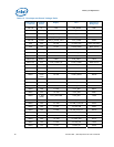
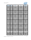
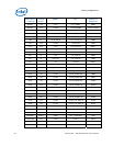
Table 12
summarizes all the power measurement resistors located on the
development board. All resistors are 0.002 Ω unless otherwise noted. Reference
designators marked with an asterisk are “not stuffed” on the development board.