


Hardware Reference
60 316704-001 / Development Kit User’s Manual
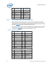
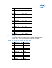
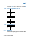
Connector J2B3 is used to power the CPU fan. Connectors J2C1 and J2F1 are not used
in the default operation of the development board.
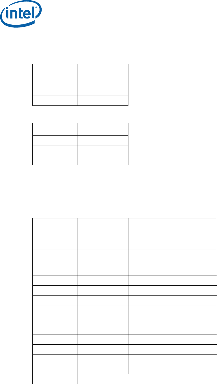
Table 26. Fan Connectors (J2B3, J2C1)
Pin Signal
1 +V
2 TACH
3 GND
Table 27. Fan Connector (J2F1)
Pin Signal
1 +5V
2 NC
3 GND
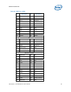
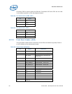
4.6.2.8 Front Panel Header (J6H5)
The front panel header allows connection of the LEDs and switches typically found in
an ATX chassis to the development board.
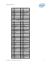
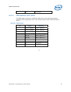
Table 28. Front Panel Connector
Pin Signal Definition
1 FRONT1 5 volt front panel LED supply
2 FRONT2 5 volt front panel LED supply
3 ATA_LED# Indicates PATA or SATA activity –
Active Low
4 GND Ground
5 GND Ground
6 PWR_CONN_D System Power – Active Low
7 RST_PUSH#_D System Reset – Active Low
8 GND Ground
9 +V5 5 volt supply
10 N/C No Connect
11 N/C No Connect
12 GND Ground
13 GND Ground
14 N/C No Connect
15 Reserved