Hardware Reference
316704-001 / Development Kit User’s Manual 59
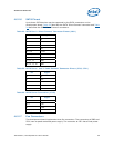
4.6.2.6 SATA Pinout
Up to three SATA devices may be supported by the SATA connectors on the
development board. Table 23
describes the SATA ‘Direct Connect’ connector and Table
24
describes the SATA ‘Cable Connect’ connectors.
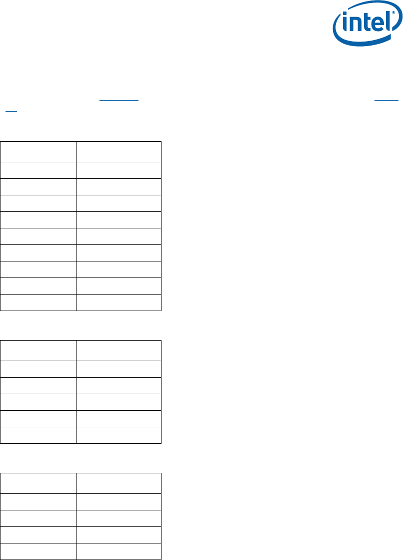
Table 23. SATA Port 0 ‘Direct Connect’ Connector Pinout (J8J1)
Pin Signal
2 TX
3 TX#
5 RX#
6 RX
8, 9, 10 +3.3V
14, 15, 16 +5V
20, 21, 22 +12V
1, 4, 7, 11 GND
12, 13, 17, 19 GND
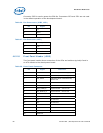
Table 24. SATA Ports 1 and 2 ‘Cable Connect’ Connector Pinout (J7J3, J7H1)
Pin Signal
2 TX
3 TX#
5 RX#
6 RX
1, 4, 7 GND
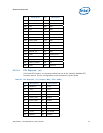
Table 25. SATA Power Connection (J7H2)
Pin Signal
1, 3 +3.3V
3, 4 +5V
5 +12V
6, 7, 8, 9, 10 GND
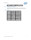
4.6.2.7 Fan Connectors
The development board implements three fan connectors. The connectors at J2B3 and
J2C1 have a speed controlled power supply. The connector at J2F1 has a fixed power
supply.


