CONTENTS
iv PEN*KEY
R
6642 Pen Computer User’s Guide
SECTION 6 6-1. . . . . . . . . . . . . . . . . . . . . . . . . . . . . . . . . . . . . . . . . .
Troubleshooting 6-1. . . . . . . . . . . . . . . . . . . . . . . . . . . . . . . . . . . .
Problems on Start-up 6Ć2. . . . . . . . . . . . . . . . . . . . . . . . . . . .
Problems with Display 6Ć3. . . . . . . . . . . . . . . . . . . . . . . . . . . .
Problems with Hard Disk 6Ć4. . . . . . . . . . . . . . . . . . . . . . . . .
Problems with Floppy Disk 6Ć4. . . . . . . . . . . . . . . . . . . . . . .
Problems with Touch Panel 6Ć5. . . . . . . . . . . . . . . . . . . . . . .
Problems with Peripherals 6Ć5. . . . . . . . . . . . . . . . . . . . . . . .
Problems with Communications 6Ć7. . . . . . . . . . . . . . . . . . .
Other Problems 6Ć8. . . . . . . . . . . . . . . . . . . . . . . . . . . . . . . . . .
Factory Service 6Ć9. . . . . . . . . . . . . . . . . . . . . . . . . . . . . . . . . .
Customer Response Center 6Ć10. . . . . . . . . . . . . . . . . . . . . . .
FIGURES
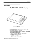
Figure 1Ć1 The PEN*KEY 6642 Pen Computer 1Ć2. . . . . . . . .
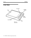
Figure 1Ć2 Front View 1Ć4. . . . . . . . . . . . . . . . . . . . . . . . . . . . . . .
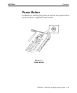
Figure 1Ć3 Power Button 1Ć5. . . . . . . . . . . . . . . . . . . . . . . . . . . . .
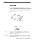
Figure 1Ć4 Pen Removal 1Ć7. . . . . . . . . . . . . . . . . . . . . . . . . . . . .
Figure 1Ć5 Side Views 1Ć8. . . . . . . . . . . . . . . . . . . . . . . . . . . . . . .
Figure 1Ć6 Rear View 1Ć9. . . . . . . . . . . . . . . . . . . . . . . . . . . . . . . .
Figure 1Ć7 Bottom View 1Ć10. . . . . . . . . . . . . . . . . . . . . . . . . . . . .
Figure 1Ć8 Reset Switch 1Ć11. . . . . . . . . . . . . . . . . . . . . . . . . . . . .
Figure 2Ć1 AC Adapter 2Ć2. . . . . . . . . . . . . . . . . . . . . . . . . . . . . .
Figure 2Ć2 Pen Operation 2Ć5. . . . . . . . . . . . . . . . . . . . . . . . . . . .
Figure 2Ć3 Connecting Devices 2Ć6. . . . . . . . . . . . . . . . . . . . . . .
Figure 2Ć4 Floppy Drive/Port Expander 2Ć7. . . . . . . . . . . . . . .
Figure 2Ć5 Floppy Drive/Port Expander Connector 2Ć8. . . . .
Figure 2Ć6 Inserting and Removing a Floppy Disk 2Ć9. . . . . .
Figure 4Ć1 Charging the Internal Battery 4Ć2. . . . . . . . . . . . . .
Figure 4Ć2 Attaching the Expansion Battery 4Ć4. . . . . . . . . . .
Figure 4Ć3 Attaching the Expansion Battery 4Ć5. . . . . . . . . . .
Figure 4Ć4 Battery Pack Capacity 4Ć6. . . . . . . . . . . . . . . . . . . . .
Figure 5Ć1 6642 Peripherals 5Ć2. . . . . . . . . . . . . . . . . . . . . . . . . .
Figure 5Ć2 Side View Connections 5Ć3. . . . . . . . . . . . . . . . . . . . .
Figure 5Ć3 SVGA Connector 5Ć5. . . . . . . . . . . . . . . . . . . . . . . . . .
Figure 5Ć4 IrDA Port 5Ć7. . . . . . . . . . . . . . . . . . . . . . . . . . . . . . . . .
Figure 5-5 Inserting the PC Card 5Ć9. . . . . . . . . . . . . . . . . . . . .
Figure 5-6 Removing the PC Card 5Ć10. . . . . . . . . . . . . . . . . . . .
Figure 5Ć7 Modem Connection 5Ć11. . . . . . . . . . . . . . . . . . . . . . . .


