


IDP 75, 250, 800, and 8200 Installation Guide
14 IDP Sensor LEDs
IDP Sensor LEDs
This section describes the LEDs for the following IDP sensor components:
System status
Management and high availability ports
Traffic ports
Hard drives
Power supply (back panel)
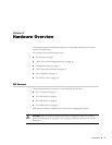
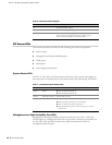
System Status LEDs
The IDP 75, 250, 800, and 8200 sensors each have three system status lights on
the front panel to indicate power, hard drive activity, and overheating. See Table 7.
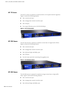
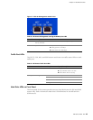
Management and High Availability Port LEDs
Management and high availability (HA) ports each have two LEDs—LINK and
TX/RX (Figure 8). Management ports are on all sensors. HA ports are available on
the IDP 250, 800, and 8200 sensors only. Table 8 describes the LEDs for
management and HA ports
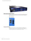
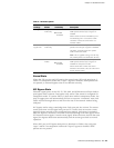
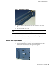
Table 6: IDP Sensor Power Supplies
IDP Sensor Power Supplies
75 One fixed power supply.
250 One removable power supply.
800, 8200 Two removable hot-swappable power supplies.
Both sensors are shipped with the AC power supply.
The DC power supplies are optional as FRUs.
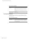
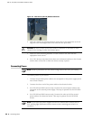
Table 7: Front Panel System Status LEDs
Color Function LED Action Status Description
Green Power Stays on when powered on.
Stays off when powered off.
Yellow Hard drive activity Flickers with activity.
Red Fault
Blinks slowly when a fan fails.
Blinks quickly when system is overheated.
Stays on when the power supply fails.
Stays off when the system is functioning at a normal
temperature.