


IDP 75, 250, 800, and 8200 Installation Guide
20 Connecting Power
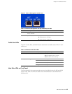
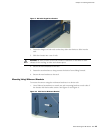
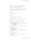
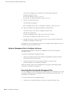
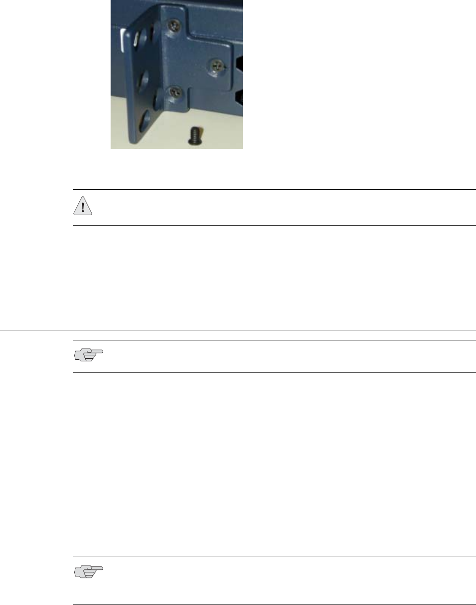
Figure 11: 1 RU Device (IDP 75) Midmount Bracket
2. Place the chassis into position between rack posts in the equipment rack and
align the rack mounting bracket holes with the rack post holes.
3. Attach the rack-mounting brackets on each chassis to the rack with the
appropriate rack screws.
4. (For 2 RU devices only) Attach the other two midmount brackets to the chassis
and the back of the rack to hold the device securely in place.
Connecting Power
To connect power to your sensor:
1. Connect the provided power cable to the receptacle on the power supply at the
rear of each chassis.
2. Connect the other end of the power cable to the electrical outlet.
3. (For IDP 800 and 8200 sensors only) Connect the second power cable to the
receptacle on the second power supply. This step is optional for the IDP 8200
sensor.
4. (For IDP 800 and 8200 sensors only) Connect the other end of the second
power cable to the electrical outlet. This step is optional for the IDP 8200
sensor.
CAUTION: Be sure to leave at least two inches of clearance on the sides of each
chassis for the cooling air inlet and exhaust ports.
NOTE: Power is provided to the IDP sensor using 90/264 VAC from your facility.
NOTE: If you have two power supplies and do not connect both of them, the PS
FAIL warning light illuminates and the sensor emits a warning tone when it is
turned on.