


IDP 75, 250, 800, and 8200 Installation Guide
28 Connecting Forwarding Interfaces
In proxy-ARP or router mode, if you are using multiple subnets in your protected
network, you must configure static routes on the IDP sensor to these subnets.
Without static routes, incoming traffic to those subnets can be lost. Alternatively,
you can create a static route from the IDP sensor to an internal gateway that
contains inbound routes to the protected subnets. (This does not apply to the IDP
8200 sensor.)
Connecting Forwarding Interfaces
Connect the ports on the sensor to either the protected network or the external
network. See “Planning an Installation” on page 1 for the configuration you chose
to implement. See “NIC Bypass and Cable Choices” on page 12 for information on
using NIC bypass with transparent mode.
Inline transparent mode makes use of pairs of interfaces. On most sensors, the
pairs are horizontal port pairs 0-1and 2-3 on each NIC. Traffic in inline transparent
mode only flows between paired interfaces. You cannot have traffic flow from port
0 to port 2, for example, in inline transparent mode.
Other modes, such as router and proxy-ARP mode, do support non-paired
interfaces.
Verifying Traffic Flow
To verify that traffic is flowing through your sensor:
1. Make sure your sensor is connected to a live traffic feed.
2. Log onto the sensor as root using the console serial port, or open an SSH
connection to the management port.
3. Type sctop and press Enter.
4. Type s to see status information.
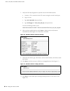
5. Examine the following information on the screen:
Protocol Packets Flows Sessions Peak Peak Time
Other 2 0 0 1 08/09/2006 03:08:07
ICMP 3 0 0 0 08/08/2006 18:03:51
UDP 3386 3 1 7 08/08/2006 19:31:01
TCP 151164 12 6 9 08/09/2006 07:01:36
6. Make sure the UDP or TCP values are changing.
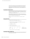
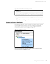
Connecting the High Availability Port
After you have set up both machines in the HA cluster, connect their HA ports to
each other using a crossover cable.