


IDP 75, 250, 800, and 8200 Installation Guide
16 IDP Sensor LEDs
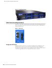
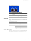
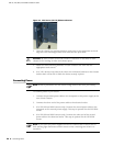
Power Supply LEDs on Back Panel
The back panel of the sensors provide access to power supplies on the 800 and
8200 sensors only. Table 11 shows the power supply LED definitions for the 800
and the 8200 sensors.
Table 10: Hard Drive LED Definitions
Front Panel LED Description
Hard drive failure (800 and
8200 only)
The left LED on the hard drive. The LED is off if the hard drive is
functioning normally. The LED is red if the hard drive has failed. In
addition, the system emits a high-pitch noise if a hard drive has
failed.
The LED flashes red if the drive is being rebuilt. Do not turn the
power off, unplug the unit, or remove either drive while the drive is
being rebuilt.
Hard drive activity
(800 and 8200 only)
The right LED on the hard drive. The LED flashes green to indicate
hard drive activity.
Table 11: Power Supply LED Definitions
Back Panel LED Description
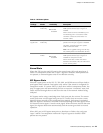
Power Supply Status (800
and 8200 only)
The LED is located on the power supply above the plug socket. It
glows amber to indicate that the power supply is receiving power. It
glows green to indicate that the power supply is powering the unit.
If a power supply has failed, or is not receiving power, the system
emits a high-pitched whine.