


3. From the PC or laptop computer, start your asynchronous terminal emulation
application (such as Microsoft Windows Hyperterminal) and select the COM port
to which the modem is connected (for example, COM1).
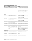
4. Configure the port settings as follows:
■ Bits per second: 9600
■ Data bits: 8
■ Parity: None
■ Stop bits: 1
■ Flow control: None
5.
In the HyperTerminal window, enter AT.
An OK response verifies that the modem communicates successfully with the
COM port on the PC or laptop.
6.
To configure the modem to answer a call on the first ring, enter ATS0=1.
7. To configure the modem to accept modem control Data Terminal Ready (DTR)
signals, enter AT&D1.
8.
To disable flow control, enter AT&K0.
9.
To save modem settings, enter AT&W.
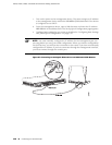
Connecting the Modem to the Console Port
NOTE: Most modems have an RS-232 DB-25 connector. You must separately purchase
an adapter to connect your modem to the RJ-45 to DB-9 adapter and Ethernet cable
supplied with the router.
To connect the dial-up modem to the console port on the router:
1. Turn off power to the router.
2. Turn off the power to the modem.
3. Plug one end of the Ethernet cable supplied with your router into the console
port on the router.
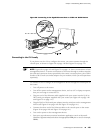
4. Plug the other end of the Ethernet cable into the RJ-45 to DB-9 serial port adapter
supplied with your router.
5. Connect the serial port adapter to a separately purchased DB-9 female to DB-25
male adapter, or other adapter appropriate for your modem.
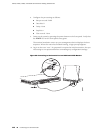
6. Plug the modem adapter into the DB-25 connector on the modem.
7. Connect the modem to your telephone network.
8. Turn on the power to the modem.
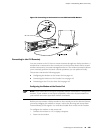
9. Power on the router by pressing the power button on the front panel. Verify that
the POWER LED on the front panel turns green.
142 ■ Connecting to a Services Router
J2320, J2350, J4350, and J6350 Services Router Getting Started Guide