


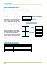
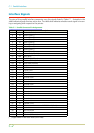
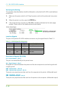
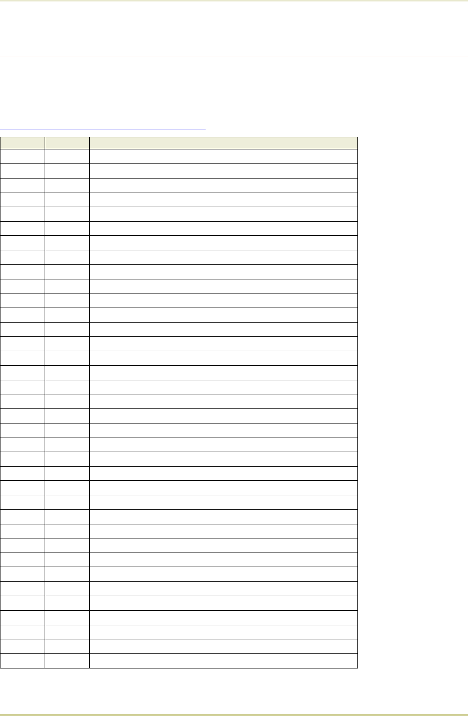
Interface Signals
The pins of the parallel interface connector carry the signals listed in Table C.1 . Asterisks in the
table indicate signals that are active low. The table also indicates whether each signal is incom-
ing or outgoing with respect to the printer.
Table C.1. Parallel Connector Pin Assignments
Pin In/out Description
1In
Strobe* [nStrobe]
2In
Data 0 [Data 1]
3In
Data 1 [Data 2]
4In
Data 2 [Data 3]
5In
Data 3 [Data 4]
6In
Data 4 [Data 5]
7In
Data 5 [Data 6]
8In
Data 6 [Data 7]
9In
Data 7 [Data 8]
10 Out
Acknowledge* [nAck]
11 Out
Busy [Busy]
12 Out
Paper Empty [PError]
13 Out
On-Line (Select) [Select]
14 In
Auto-feed [nAutoFd]
15 —
Not connected
16 —
0V DC
17 —
Chassis GND
18 —
+5V DC
19 —
Ground return
20 —
Ground return
21 —
Ground return
22 —
Ground return
23 —
Ground return
24 —
Ground return
25 —
Ground return
26 —
Ground return
27 —
Ground return
28 —
Ground return
29 —
Ground return
30 —
Ground return
31 In
Ignored [nInit]
32 Out
Error*, returns error status if FRPO O2=2 [nFault]
33 —
—
34 —
Not connected
35 Out
Power Ready
36 In
Select In [NSelectIn]
[ ]: Signal names in the Auto mode. (IEEE 1284)
C.1. Parallel Interface
C-2