


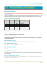


C.4. RS-232C Cable Connection
Preparing an RS-232C Cable
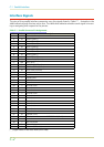
After obtaining an RS-232C cable, check that it is wired correctly, referring to the pin assign-
ment table in Appendix C. If you have an IBM communication adapter cable type 1502067,
you will have to resolder the wiring at the printer end of the cable. The procedure is as fol-
lows.
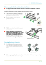
1.
Unscrew the plastic cover from the printer end of the cable.
2.
Next to each of the wires inside the cable is a bare shield wire. Solder all these shield
wires together into a single bundle.
3.
Using a section of flat wire about 3 mm wide and 15 mm long, connect the bundle of
shield wires to the metal facing of the connector. Check that the solder connections are
secure.
4.
Desolder wires 2 and 3, then resolder them in crossed configuration. Solder wire 2 to pin
3 and wire 3 to pin 2. Cover the solder joints with thermofit tube.
5.
Cut wires 4, 5, 6, and 20.
6.
Solder wires 5 and 6 together and connect them to pin 20. Cover the solder joints with
thermofit tube. Leave wire 4 unconnected.
7.
Tape all remaining loose ends, or seal them with thermofit tube.
8.
Screw the plastic cover back on.
Connecting the Printer to the Computer
1.
Check that the power of both the printer and computer is switched off.
2.
Discharge yourself by touching a metal object such as a doorknob.
3.
Remove the plastic cap from the printer’s RS-232C interface connector.
4.
Plug the printer end of the RS-232C interface cable into the printer’s RS-232C connector
and screw it in place.
5.
Plug the other end of the cable into the computer’s RS-232C interface connector.
6.
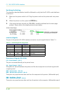
Switch on the printer’s power.
7.
The printer’s RS-232C parameters are factory-set to the following values:
C.4. RS-232C Cable Connection
C-12