


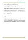
Verifying the Setting
The procedure described below should be followed to verify that the RS-422A mode had been
correctly set.
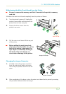
1.
Make sure the power switch is off. Plug the power cord into the printer and turn power
on.
2.
When the printer is on-line, press the STATUS key.
3.
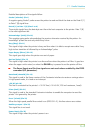
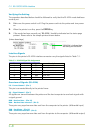
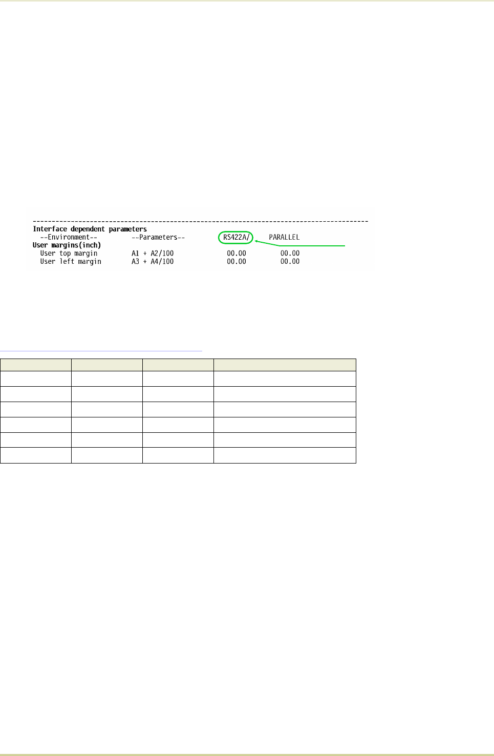
If the mode has been correctly set, "
RS-422A
" should be indicated on the status page
printout. Please refer to the sample printout shown below.
Interface Signals
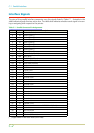
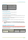
The pins in the printer’s RS-422A interface connector carry the signals listed in Table C.3 .
Table C.3. RS-422A Signal Pin Assignments
Pin In/out Signal Description
1–FG
Frame ground
3InRDA
Receive data Inverted
7–SG
Signal ground
9OutSDA
Send data Inverted
10 Out SDB
Send data
18 In RDB
Receive data
Overview of Signals (RS-422A)
FG – Frame Ground – (Pin 1)
This pin is connected directly to the printer frame.
SG – Signal Ground – (Pin 7)
All signals can transmit between the printer and the host computer to send each signals with
a signal ground.
RDB – Receive Data – (Pin 18)
RDA – Receive Data Inverted – (Pin 3)
These pins carry asynchronous data sent from the computer to the printer. (differential input)
SDB – Send Data – (Pin 10)
SDA – Send Data Inverted – (Pin 9)
These pins carry asynchronous data sent from the printer to the computer. (differential output)
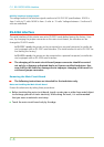
If RS-422A is indicated here,
the setting was successful.
[Printer Status Page]
C.2. RS-232C/RS-422A Interface
C-8