


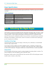
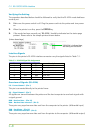

Detailed descriptions of the signals follow.
Strobe* [nStrobe] (Pin 1)
A negative-going Strobe* pulse causes the printer to read and latch the data on the Data 0 [1]
to Data 7 [8] signal lines.
Data 0 [1] to Data 7 [8] (Pins 2 to 9)
These eight signals form the data byte sent from the host computer to the printer. Data 7 [8]
is the most significant bit.
Acknowledge* [nAck] (Pin 10)
This negative-going pulse acknowledges the previous character received by the printer. Ac-
knowledge* pulses are sent only when Busy is low.
Busy [Busy] (Pin 11)
This signal is high when the printer is busy and low when it is able to accept more data. Every
high-to-low transition is followed by an Acknowledge* pulse.
Paper Empty [PError] (Pin 12)
This signal goes high when the printer runs out of paper.
On-Line [Select] (Pin 13)
This signal is high when the printer is on-line and low when the printer is off-line. It goes low
when the upper unit is raised, or when the ON LINE key is pressed to set the printer off-line.
The Paper Empty and On-Line signals are not used unless enabled by the FRPO
command (O2 parameter).
Auto-Feed [nAutoFd] (Pin 14)
This signal is used in the Epson version of the Centronics interface to receive a carriage return.
In high-speed mode, it is used as an interrupt.
+5V DC (pin 18)
This line is connected to the printer’s +5V DC line (+5V 0.5V, 250 mA maximum, fused).
Prime [nInit] (Pin 31)
This signal is used in the standard Centronics interface to enable the computer to reset the
printer. It is ignored by the printer.
Error* [nFault] (Pin 32)
When the high-speed parallel line control is on (FRPO O2=2), this line returns error status.
Auxiliary output 1 (Pin 33)
This signal line is not used.
Power Ready (Pin 35)
This signal is high when the printer’s power is on.
±
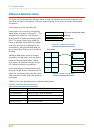
C.1. Parallel Interface
C-3