


XPress DR+ User Guide 18
Chapter 3: Installation and Hardware
What's in the Box?
Verify and inspect the contents of the package using the enclosed packing slip or
the list below. If any item is missing or damaged, contact your place of purchase
immediately.
XPress DR+ or XPress DR+W
Resource CD
Quick Start Guide
P/N: 500-103 RJ45-DB9F serial cable.
P/N 930-029 antenna (XPress DR+W only)
Accessory DIN-rail wall mount bracket
3 terminal screw connector for power input
5 terminal screw connector for serial port
What Must the User Provide?
9-30 VDC or 9-24 VAC power source
CAT 5 Ethernet cable (for wired XPress DR+ and the wireless version operating
in wired mode)
Physically Connecting the XPress DR+
Note: for information on physically connecting the XPress DR+W in wireless
mode, see Chapter 4: XPress DR+W.
Note: To comply with the hazardous location approval of the XPress DR+, the unit must
be installed in a tool-secured enclosure and wiring must be installed in accordance with
Division 2 wiring practices as specified by the NEC.
This section describes the procedures for getting your unit up and running. For a short
version, see the Quick Start Guide. Detailed descriptions of the hardware components of
the XPress DR+ follow this simple installation procedure.
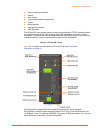
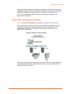
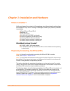
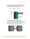
The following diagram shows the basic connectivity of an XPress DR+ to the network and
a serial device. The Lantronix-supplied P/N: 500-103 serial cable can be used on the
RJ45 RS232 serial ports to connect the XPress DR+ to a PC or to a serial device that
has a DB9M RS232 DTE interface. If the device being connected uses a different serial
interface, please refer to page 22 for the serial interface pinout or to Appendix B:
Lantronix Cables and Adapters for a list of serial cables or adapters.