


Contents
XPress DR+ User Guide 8
Australia & New Zealand – Wireless Notice __________________________________ 114
Appendix F: Warranty 115
Index 116
Figures
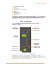
Figure 2-1. XPress DR+ (Front) .......................................................................... 13
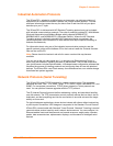
Figure 2-2. Example of Serial Tunneling ............................................................. 15
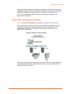
Figure 2-3. Example of Cascading Multiple XPress DR+ Units .......................... 16
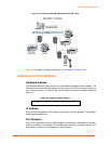
Figure 2-4. Sample Hardware Address ............................................................... 16
Figure 3-1. Typical Configuration ........................................................................ 19
Figure 3-2. Front of XPress DR+ ......................................................................... 20
Figure 3-4. Screw Terminal Ports ........................................................................ 21
Figure 3-5. Termination Resistor for 2-Wire Connection ..................................... 22
Figure 3-6. Lantronix P/N 500-103 RJ45-DB9F Serial Cable Pinout .................. 22
Figure 3-7. Multi-Drop Ethernet Connections ...................................................... 24
Figure 3-8. Reset Switch ..................................................................................... 25
Figure 3-9. LEDs on the XPress DR ................................................................... 25
Figure 3-10. Dimensions ..................................................................................... 26
Figure 3-11. Wall Mount Bracket ......................................................................... 27
Figure 3-12. Product Label .................................................................................. 27
Figure 4-1. Serial Tunneling Infrastructure Network Example ............................ 28
Figure 4-2. Ad Hoc Network Example ................................................................. 29
Figure 4-3. Serial Tunneling Infrastructure Example ........................................... 29
Figure 4-4. Direct XPress DR+W - to- XPress DR+W Connection ..................... 30
Figure 4-5. Typical XPress DR+W Configuration ................................................ 31
Figure 4-6. XPress DR+W Front Panel Layout ................................................. 31
Figure 4-7. Network Mode ................................................................................... 34
Figure 4-8. Server Settings .................................................................................. 34
Figure 6-1. Lantronix Web Manager .................................................................... 46
Figure 6-2. Network Settings ............................................................................... 47
Figure 6-3. Server Settings .................................................................................. 49
Figure 6-4. Hostlist Settings ................................................................................ 50
Figure 6-5. Channel Serial Settings .................................................................... 52
Figure 6-6. TCP Connection Settings .................................................................. 54
Figure 6-7. UDP Connection Settings ................................................................. 57
Figure 6-8. WLAN Settings – Ad Hoc Network Type .......................................... 59
Figure 6-9. WLAN Settings – Infrastructure Network Type ................................. 60
Figure 7-1. MAC Address .................................................................................... 64
Figure 7-2. Setup Menu Options ......................................................................... 64
Figure 8-1. Network Mode ................................................................................... 66
Figure 8-2. Server Settings .................................................................................. 66
Figure 9-1. Serial Port Parameters ...................................................................... 69
Figure 9-2. Manual Connection Address Example .............................................. 74
Figure 9-3. Hostlist Option ................................................................................... 75
Figure 10-1. Expert Settings ................................................................................ 88
Figure 10-2. Security Settings ............................................................................. 89
Figure 11-1. TFTP Window ................................................................................. 94
Figure 12-1. Accessing Monitor Mode ................................................................. 96