


Chapter 3: Installation and Hardware
XPress DR+ User Guide 22
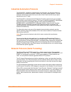
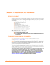
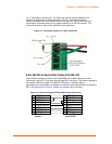
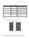
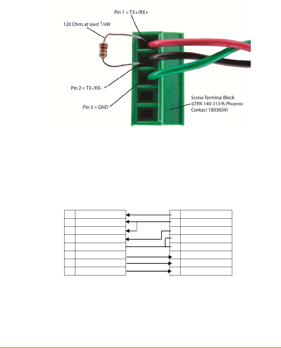
Note: Termination resistors (R = 120 Ohm) are used to match impedance of a
node to the impedance of the transmission (TX) line. Termination resistors
should be placed only at the extreme ends of the data line, and no more than two
terminations should be placed in any single segment of an RS-485 network. The
termination resistors may not be needed for your application.
Figure 3-5. Termination Resistor for 2-Wire Connection
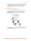
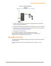
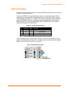
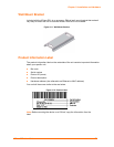
9-Pin RS-232 to Serial RJ45 Cable (P/N 500-103)
The included Lantronix (P/N 500-103) RJ45-DB9F serial cable assumes you are
connecting a typical PC Com port to the XPress DR+ serial port. This cable is pinned to
provide full serial line control to an RS232 DTE device. Lantronix offers a
comprehensive list of cables and adapters to simplify device connectivity to the XPress
DR+. See Appendix B: Lantronix Cables and Adapters for a full listing.
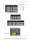
Figure 3-6. Lantronix P/N 500-103 RJ45-DB9F Serial Cable Pinout
8 CTS (In) 1 RTS (Out)
1 DCD (In) 2 DTR (Out)
6 DSR (In) 3 TXD
2 RXD (In) 4 Signal Ground
5 Signal Ground 5 Signal Ground
3 TXD (Out) 6 RXD
4 DTR (Out) 7 DSR (In )
7 RTS (Out) 8 CTS (In)
DTE, 9-Pin XPress DR+
Female Serial RJ45