


Chapter 3: Installation and Hardware
XPress DR+ User Guide 21
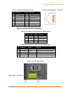
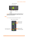
Table 3-1. RJ45 Serial Connector Pinouts
Pin Direction Name Function
1 Output from DR+ RTS Ready To Send
2 Output from DR+ DTR Data Terminal Ready
3 Output from DR+ TXD Transmitted Data
4 Ground GND Signal Ground
5 Ground GND Signal Ground
6 Input to DR+ RXD Received Data
7 Input to DR+ DSR Data Set Ready
8 Input to DR+ CTS Clear To Send
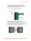
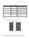
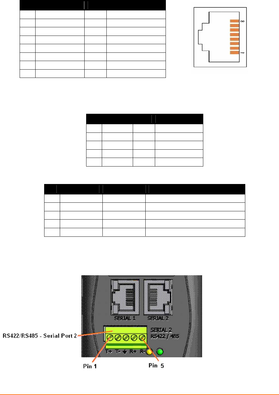
Screw Terminal Serial Connectors
Table 3-2. Serial Screw Terminal Pinout for RS422 (4-Wire)
Pin Direction Name Function
1 Output TX+ Transmit Data +
2 Output TX- Transmit Data -
3 Ground GND Signal Ground
4 Input RX+ Received Data +
5 Input RX- Received Data -
Table 3-3. Serial Screw Terminal Pinout for RS485 (2-Wire)
Pin Direction Name Function
1 Bi-directional TX+/RX+ Transmit Data + and Received Data +
2 Bi-directional TX-/RX- Transmit Data – and Received Data -
3 Ground GND Signal Ground
4 Not Applicable Not Applicable Not Used
5 Not Applicable Not Applicable Not Used
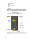
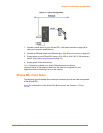
Figure 3-4. Screw Terminal Ports
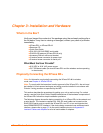
Figure 3-3. RJ45 Connector – Front View