Connecting the cables
Attention: To prevent damage to equipment, connect the power cords last.
If the server cables and connector panel have color-coded connectors, match the
color of each cable end with the color of the connector. For example, match a blue
cable end to a blue connector on the panel, a red cable end with a red connector,
and so on.
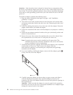
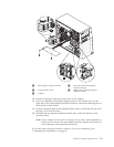
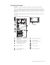
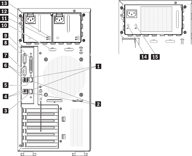
The following illustration shows the input/output (I/O) connectors on the rear of
the server.
Table 10. Connectors on the rear of the server
1 Ethernet transmit/ receive activity
LED (amber)
8 Serial 1 (Com1) connector
2 Ethernet link status LED (green) 9 Parallel connector
3 Remote Supervisor Adapter II
SlimLine (Ethernet) connector
10 Serial 2 (Com2) connector
4 USB connectors 1 and 2 11
and
15
DC power LED
5 Ethernet connector 12
and
14
AC power LED
6 USB connectors 3 and 4 13 Power cord connector
7 Video connector
Chapter 2. Installing optional devices 33


