


50
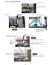
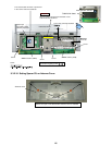
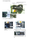
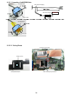
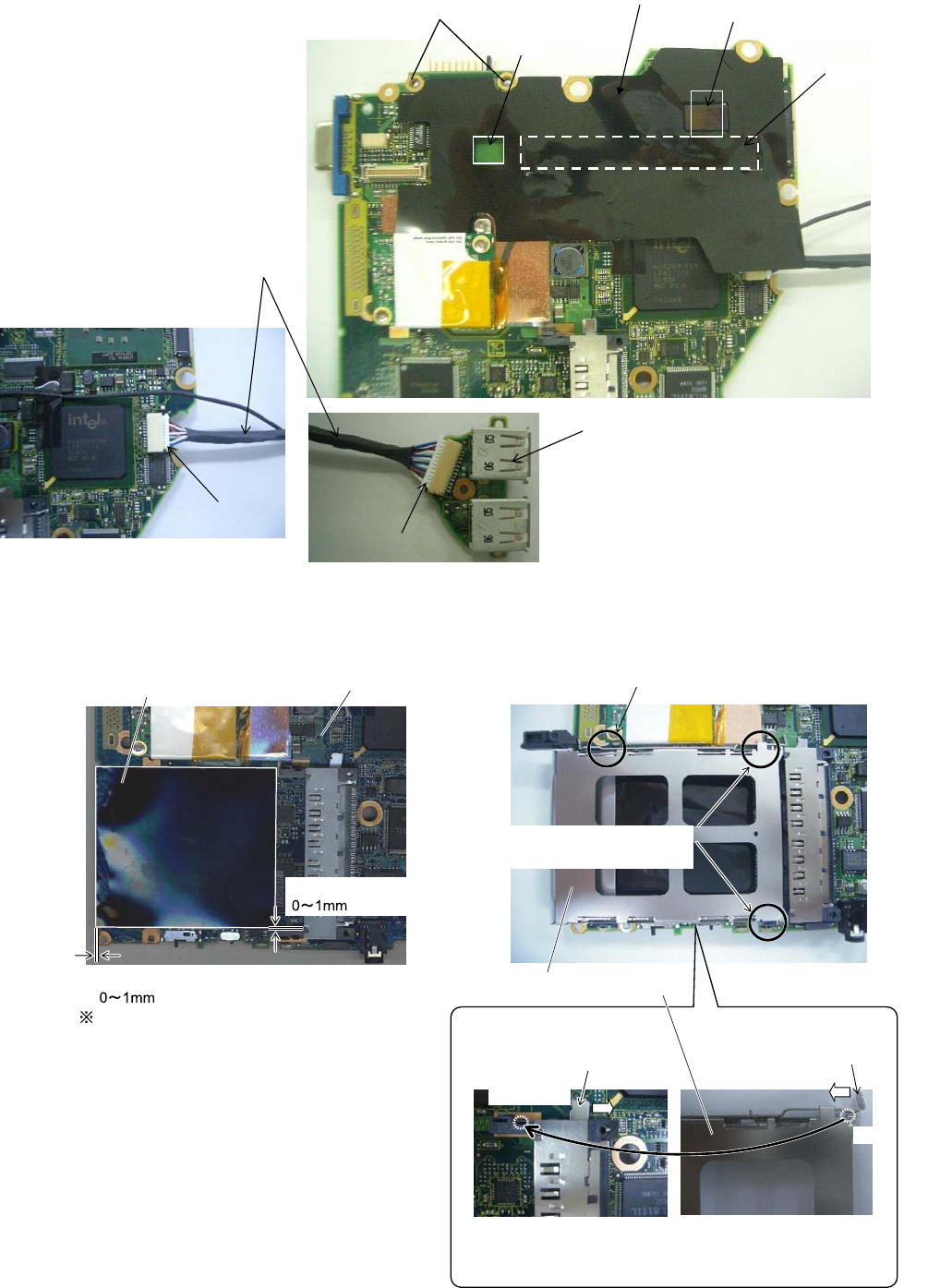
9.3.3.4. Putting Main PW Sheet
Main sub cable
USB b oard
MAIN PWB sheet 1 W5
Connector connectionConnector connection
Connector connectionConnector connection
Two sided tape putting
Square hole
Square hole
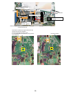
Do not get on the
machine screw hole
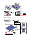
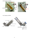
Corner hole part DAI of the CIP set is matched and affixes
Affix without running aground on CPU DAI.
Board externals match
There must not be disarrangement from
board externals.
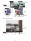
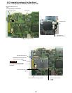
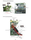
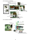
PCMCIA-MAIN sheet
Main board
Touch the power SW edge
Insert on the tip of the foot under of MDC board
Refer to the explanation
for the installation.
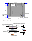
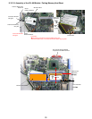
The lever is drawn to
the right before building in
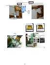
Card bus ejector
The lever is drawn to the
left before building in.
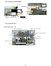
Card bus ejector’s sheet metal bend part is inserted in
the corner hole part. (An opposite direction is also the same)
Multiply the hook surely. (There must not be floatage)
Square hole
Bend
Explanation
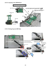
9.3.3.5. Assembly of the PCMCIA Ejector