


P. P.
Rev. P. Dokument N Signature Data
ТЭ3.623.912-03РЭ
ТЭ3.623.912-03РЭ
Rev. P. Dokument N Signature Data
Size А3 /А4
Signature and Data
Invent N of doubl
Subst. of invent N
Signature and Data
Invent N of orig.
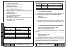
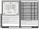
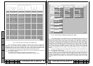
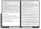
Fig.4 –ACS Frame No.2 "STATE OF МТК-110МЭ TVDs".
The "ON" column contains the numbers of the CPs, from which the TVDs were
switched on. If the same TVD was switched on from several CPs, their numbers are
displayed via blanks. The device including the ЭМ-1212-1 control module and the ВС-2 TVM
is designated as CP No.4 of the TV-complex. The "CTRL" column shows the number of a CP
of the TV-complex and the remote control command being executed from this CP.
The "CHECK" column shows the number of CP of the TV-complex from which the
TVD was chosen for servicing.
The number of ACS frame No.2 is shown in the right lower corner.
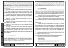
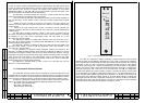
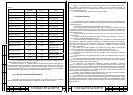
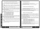
The ACS frame No.3, "MODULE FEEDING VOLTAGES" is shown in Fig.5.
Fig. 5 – ACS Frame No.3 "MODULE FEEDING VOLTAGES".
The feeding voltages are symbolically shown as horizontal lines with four marks. The
leftmost mark represents the zero point. The next three marks represent the minimum,
nominal and maximum values of the voltage. The length of a line denotes the voltage in a
non-linear scale. The position of the minimum mark corresponds to 95% of the rated voltage.
The position of the rightmost mark corresponds to 105% of the rated voltage. If the voltage
controlled falls out of the tolerance limits, the line blinks that is a sign of a fault in the module.
The output voltages of the three ЭМ-1213 power supply units are displayed in the upper part
of the frame. The supply voltages produced by power supply cells in the corresponding
modules are displayed below. The number of ACS frame No.3 is shown in the right lower
corner.
Frames are switched over by pressing the arrow buttons on the front panel of the
ЭМ-1211 diagnostics module (Fig.2).
The ЭМ-1212-1 control module indicates faulty modules of the TV-complex with the
LEDs, in accordance with the information received from the ЭМ-1211 diagnostics module via
the RCLI channel. Light-up of the LED of the МТК-110МЭ indicates a fault in some unit or
module not represented on the ЭМ-1212-1 control module front panel. To get more specific
information about the faulty module, the ACS frame No.1 should be output on the TVM
screen.
19
20
N
NAME
CODE
ON
CTRL
CHECK
1-1
1-2
1-3
PERISKOPE
FE-6F
R
1
R
1D STB
КТ-257
ТМ–1220-1
НЕОТОН-08-2
1
2 3
----
1 DAY
2 TEST
---
---
---
1
1-4
2-1
2-2
2-3
1
R
2D
1
R
1D PS
SUPRST
R
20F
R
3
R
1D
НЕОТОН-08-1
НЕОТОН-08-1
ТМ–1220-1
НЕОТОН-08-2
4
----
----
----
---
---
---
---
---
---
---
---
2-4
3-1
3-2
3
R
3D
4
R
1D
WINCH ACS
НЕОТОН-08
НЕОТОН-08-2
ТМ–1220-1
----
----
----
---
---
---
---
---
---
3-3
3-4
4-1
4-2
4
R
2D STB
4
R
2D PS
5
R
PS
5
R
STB
НЕОТОН-08-1
НЕОТОН-08-1
НЕОТОН-08-2
НЕОТОН-08-2
----
----
----
----
---
---
---
---
---
---
---
---
4-3
4-4
5-1
WINCH SS
4
R
2D PCS
6
R
1D A
ТМ–1220-1
НЕОТОН-08
НЕОТОН-08-1
----
----
----
---
---
---
---
---
---
5-2
5-3
5-4
6
R
1D F
TC
POD 108F
R
НЕОТОН-08-1
НЕОТОН-08
ТМ–1220-1
----
----
----
---
---
---
---
---
---
STATE
OF
МТК
–
110МЭ
TVDs
N2
+6V1
+6V2
+6V3
-6V1
+27V1
+27V2
+5V
-5V
ЭМ–1204-1
+5V
ЭМ–1205-1
+5V
ЭМ–1209-1
+5V
ЭМ–1242
N1
ЭМ-1213
MODULE FEEDING VOLTAGES
N3
N2 N3