


Rev. P. Dokument N Signature Data
ТЭ3.623.912-03РЭ ТЭ3.623.912-03РЭ
Rev. P. Dokument N Signature Data
Size А3 /А4
Signature and Data
Invent N of doubl
Subst. of invent N
Signature and Data
Invent N of orig.
- remove the module from its place by careful pulling it out.
Installation of the serviceable module from the BSP into the device is done as follows:
- set the horizontal central slide rails of the module into the slots in the device;
- push in the module up to the stop, about 10 cm off the final position;
- by turns put the wrench into the slots of the left and the right locks of the module and
turn it clockwise by 30-60º each time. Acting as described above, move the module into the
working position;
- put on the captive screws on the module (unit) front panel.
3.1.4.3 Replacement of the ФСП-3В interference rejection filter (hereinafter referred to
as “filter”) is done as follows:
- undo the screws fastening the cover in the lower part of the device rear wall;
- remove the cover and put it aside;
- take the soldering iron out of the toolkit; connect it to the plug-transformer for 24V;
- unsolder the wires off the contacts of the filter, mark them and move them aside;
- undo the screws fastening the ФСП-3В in the device;
- take out the ФСП-3В;
- install the serviceable ФСП-3В from the DSP in the place of the faulty one;
- fix the ФСП-3В with the screws;
- solder the wires to the contacts of the ФСП-3В;
- switch the soldering iron off;
- install the cover and fix it with the screws.
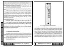
3.1.4.4 Replacement of the ВС-2 TVM is done as follows:
- undo the four captive screws in the corners of the ВС-2 TVM front panel;
- pull the handles and move the ВС-2 TVM out of the device up to the stop on the
telescopic holders;
- remove the cable connectors linking the ВС-2 TVM with the device;
- undo the screws fastening the ВС-2 TVM to the movable base;
- take the ВС-2 TVM out of the device;
- mount the serviceable ВС-2 TVM from the BSP on the movable base of the device;
- fasten the ВС-2 TVM on the movable base with the screws;
- fix in the cable connectors linking the ВС-2 TVM with the device;
- push in the ВС-2 TVM into the device until it stops in the working position;
- put on the captive screws on in the corners of the BC-2 TVM front panel.
3.1.4.4.1 Replacement of the ЭМ-1229 video adapter and ЭМ-1239 power supply unit
in the ВС-2 TVM is done as follows:
- remove the ВС-2 TVM out of the device (see item 3.1.4.4);
- put the ВС-2 TVM on a smooth and plane surface with its face side down;
- undo the screws on the rear wall of the ВС-2 TVM;
- open the rear wall of the ВС-2 by an angle exceeding 90 deg.;
- undo the four screws, fastening the faulty unit to the two laths on the rear wall;
- unplug the unit off the connector;
- install the serviceable unit from the BSP instead of the faulty one and fasten it with
the screws;
- install the rear wall and fasten it with the screws;
- install the TVM into the device (see item 3.1.4.4).
3.1.5 Device Operability Check-Up
Testing the device while maintaining it is to be done in accordance with item 2.2.5 of
the present Manual.
P. P.
38
37