


Size А3 /А4
Signature and Data
Invent N of doubl
Subst. of invent N
Signature and Data
Invent N of orig.
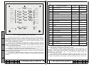
Light-up of one of the LEDs on the ТМ-1304 No.1 – ТМ-1304 No.5 combined modules
on the ЭМ-1212-1 control module front panel means that either one of the modules
comprised by the ТМ-1304 combined module is malfunctioning or the TVD working with this
combined module is out of order. To localize the faulty module, the ACS frame No.1 should
be output on the TWM screen.
Light-up of the FUSE diode on the front panel of the ЭМ-1212-1 control module means
that one of fuses F1-F16 installed on the fifth floor of the device is blown out. To localize the
faulty fuse, the ACS frame No.1 should be output on the TVM screen.
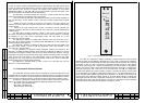
Information acquisition and control of the indication LEDs of the ЭМ-1212-1 control
module is performed by the microcontroller and PLIC of the ACS. The ЭМ-1212-1 control
module is installed in the middle of the second floor of the device. The device door has a
glassy window opposite to the ЭМ-1212-1 control module thereby allowing observation on
the state of the TV-complex when the door is closed.
1.1.4.5 Chronometrical Information Input System
The chronometrical information input system receives chronometrical data via
separate serial channels from device "Гном-2МЭ", transmits it to the external ТМ-1213
terminal module for mixing into the video signal during video recording and displays this data
on the screen of the ВС-2 TVM.
The main unit of the chronometrical information input system is the ЭМ-1242 interface
unit. The signals of the main and reserved channels of device "Гном-2МЭ" are supplied to
the interface unit via connectors Х40 and Х41. The MC and PLIC of the ЭМ-1242 interface
unit perform processing of these signals, reception of the incoming arrays containing
chronometrical information and writing the data to the internal RAM of the PLIC.
On request from the ЭМ-1209-1 controller the MC forms a reply array that is
transferred to the ЭМ-1209-1 controller via a RCLI channel.
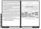
The ЭМ-1209-1 controller periodically interrogates the ЭМ-1242 interface unit, forms
data arrays containing date and time and transfers them to the ТМ-1213 terminal module
and ЭМ-1211 diagnostics module. The latter displays the date and the time received
from each of the "Гном-2МЭ" channels in ACS frame No.1. In case of absence of the
information in one of the "Гном-2МЭ" channels, dashes are displayed in ACS frame
No.1.
1.1.4.6 Power Supply System
The power supply system provides secondary feeding voltages for the units and
modules incorporated by the device as well as some other units of the TV-complex.
The power supply system comprises the following device modules:
- assemble unit (A1);
- interference rejection filters, the ФСП-3В (A2 - A7);
- power supply unit, the ЭМ-1213 (A61, A71, A72);
- fuses F1 - F16;
- power supply cells that are parts of the ЭМ-1204-1 and ЭМ-1205-1 videoswitch
modules, ЭМ-1209-1 controller, ЭМ-1211 diagnostics module, ЭМ-1212-1 control module
and ЭМ-1242 interface unit.
The three-phase feeding voltage 220 V, 50 Hz from the ЩР-03 switchboard is
supplied to the device via a cable through connector XP1 and the assembly unit (A1). The
device is switched on with toggle switch POWER. The three-phase voltage form the switch
arrives to the indicator lamps through the three fuses and then - to PCB XT1 of the assembly
unit. The switch and the fuses are found under the drop cover on the assembly unit front
panel. The lamps indicating presence of feeding voltage 220 V,50 Hz are mounted on the
assembly unit front panel.
The three-phase feeding voltage 220 V, 50 Hz from assembly unit PCB XT1 through
PCB XT1 of the device is supplied to the ФСП-3В interference rejection filters (A2 - A7) and
then – to the ЭМ-1213 power supply units (A61, A71, A72). The ЭМ-1213 power supply units
are connected to different phases of the three-phase mains.
Each of the ЭМ-1213 power supply units has six galvanically decoupled d.c. outputs
with the following parameters:
- one 27 V output with a current of up to 4 A;
- one 27 V output with a current of up to 2 A;
- four 6 V outputs with a current of up to 2 A.
All the d.c. power supplies in the ЭМ-1213 power supply units have overcurrent and
short-circuit protections that are automatically reset when the overload conditions are
removed.
The 6 V supply voltages produced by the ЭМ-1213 power supply units are used for
feeding the modules of the device. The feeding voltage of plus 6 V is provided by connecting
the negative terminals of the 6 V power supply units to the common bus, whereas for
obtaining a feeding voltage of minus 6 V the plus 6 V power supply units are connected vice
versa. The 6 V supply voltages are supplied to the device modules through PСB AP2 of the
device.
All the device modules that are supplied with the plus 6 V and minus 6 V voltages are
fed from two or three ЭМ-1213 power supply units simultaneously. This ensures operability of
the device in case of failure of one of the ЭМ-1213 power supply units.
The modules consuming the plus 6 V and minus 6 V voltages contain power supply
cells that form their own feeding voltages, provided at least one of the ЭМ-1213 power supply
unit voltages is present. The internal supply voltages of the consuming modules are
connected to the ЭМ-1211 diagnostics module inputs for control.
The BC-2 TVM is fed from the ЭМ-1213 power supply unit (A72) with the plus 27 V
voltage. The ЭМ-1239 power supply installed into the BC-2 TVM produces its own supply
voltages of plus 12 V and plus 5 V.
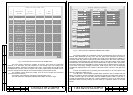
The plus 27 V voltage from the other outputs of the ЭМ-1213 power supply unit is
distributed among various units and modules of the TV-complex, passing through PCB AP1
and fuses F1-F16 to the output connectors of the device. The fuses protect the power
supplies against short-circuits in each of the loads. The fuses are installed on a panel on the
fifth floor of the device. There is a LED near each of the fuses indicating presence of the plus
27V voltage on the fuse output.
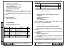
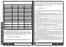
The external loads of the plus 27 V supply voltage of the ЭМ-1213 power supply units
are shown in Table 3.
P. P.
Rev. P. Dokument N Signature Data
ТЭ3.623.912-03РЭ
ТЭ3.623.912-03РЭ
Rev. P. Dokument N Signature Data
22
21