


Size А3 /А4
Signature and Data
Invent N of doubl
Subst. of invent N
Signature and Data
Invent N of orig.
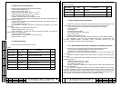
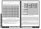
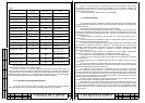
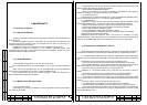
Table 3
+27V power supply unit
fuse
number
Device external
connector
External
load
ЭМ-1213 No.1 (А61) F1 Х32 ТМ-1304 No.1
ЭМ-1213 No.3 (А72) F2 Х32 ТМ-1304 No.1
ЭМ-1213 No.2 (А71) F3 Х33 ТМ-1304 No.2
ЭМ-1213 No.3 (А72) F4 Х33 ТМ-1304 No.2
ЭМ-1213 No.3 (А72) F5 Х34 ТМ-1304 No.4
ЭМ-1213 No.1 (А61) F6 Х34 ТМ-1304 No.4
ЭМ-1213 No.1 (А61) F7 Х35 ТМ-1304 No.5
ЭМ-1213 No.2 (А71) F8 Х35 ТМ-1304 No.5
ЭМ-1213 No.2 (А71) F9 Х36 ТМ-1304 No.3
ЭМ-1213 No.3 (А72) F10 Х36 ТМ-1304 No.3
ЭМ-1213 No.3 (А72) F11 Х37 Reserved
ЭМ-1213 No.1 (А61) F12 Х37 Reserved
ЭМ-1213 No.1 (А61) F13 Х38
ТМ-1213,
ТМ-1215-4 No.1,
ТМ-1215-4 No.2
ЭМ-1213 No.2 (А71) F14 Х38
ТМ-1213,
ТМ-1215-4 No.1,
ТМ-1215-4 No.2
ЭМ-1213 No.2 (А71) F15 Х39 ТМ-1215-4 No.3
ЭМ-1213 No.3 (А72) F16 Х39 ТМ-1215-4 No.3
The ТМ-1308 assembly modules and ТМ-1201 terminal modules via which the 27 V
voltage passes in transit are not shown in Table 3.
All the 27 V and 6 V d.c. voltages produced by the ЭМ-1213 power supply units are
fed to the analog inputs of the ЭМ-1211 diagnostics module (A21). The ЭМ-1211 diagnostics
module performs continuous tolerance check-up of these voltages. Also fed to the ЭМ-1211
diagnostics module are the 27 V d.c. voltages from the outputs of fuses F1-F16 and voltages
from internal power supply cells of the modules that are parts of the device.
1.1.4.7 Auxiliary Communication System
The auxiliary communication system provides wire duplex communication between
different modules of the TV-complex that is used during servicing of the complex.
There is a connector X42 for connecting the auxiliary communication device (ACD).
The auxiliary communication lines come in parallel to the TV-complex modules via
connectors X32-X39. The +27 V feeding voltage is applied to an ACL via a current-limiting
resistor for feeding the ACD.
The ТС-0120 ACD is included into the TV-complex BSP.
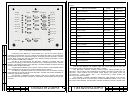
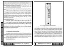
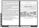
1.1.4.8 Device Design
As per design the device constitutes a splash-proof cabinet with an amortization base.
The general view of the device is shown in Fig. B1 (appendix B). The floors of the cabinet are
numbered top-down.
The modules comprised by the device are located as follows.
In the upper part of the cabinet the assembly unit (1) is installed. The feed switch and
the fuses are mounted under the drop cover (23) to the left of the assembly unit front panel.
The indicators (28) of phase voltage presence (220 V,50 Hz) are fastened on the front panel
of the assembly unit.
The ВС-2 TVM (2) is installed on the first floor. The TVM can be pulled out on a
movable base.
On the second floor are installed the ЭМ-1211 diagnostics module (3), ЭМ-1212-1
control module (4) and ЭМ-1242 interface unit (5).
On the third floor are installed (from left to right): the ЭМ-1204-1 videoswitch module
(6), ЭМ-1205-1 videoswitch module (7), ЭМ-1204-1 videoswitch module of the BSP (8),
ЭМ-1205-1 videoswitch module of the BSP (9), ЭМ-1211 diagnostics module of the BSP
(10), ЭМ-1209-1 controller of the BSP (11), ЭМ-1209-1 controller of the BSP (12) and
ЭМ-1209-1 controller (13).
The fourth floor contains modules of the BSP such as the ЭМ-1211 diagnostics
module (14), ЭМ-1212-1 control module (15) and ЭМ-1242 interface unit (17).
On the fifth floor are installed the panel (17) with fuses F1-F16 and the LEDs.
The ЭМ-1213 No.1 (18) power supply unit and ЭМ-1213 (19) of the BSP are installed
on the sixth floor.
On the seventh floor are installed the ЭМ-1213 No.2 and ЭМ-1213 No.3 (18) power
supply units.
The ФСП-3В interference rejection filters are mounted near the connectors of the
ЭМ-1213 power supply units under the rear cover (21) of the cabinet. There are two ФСП-3В
interference rejection filters per power supply unit.
The ЭМ-1204-1 and ЭМ-1205-1 videoswitch modules, ЭМ-1209-1 controllers,
ЭМ-1211 diagnostics modules, ЭМ-1212-1 control modules, ЭМ-1213 power supply units
and ЭМ
-1242 interface units constitute a frame with two horizontal slide rails. On the frames
are mounted one or two PCBs with connectors. The front panel of the module is fastened to
the frame. There are slide ways for each module in the cabinet. This modules are fixed in the
working position with special locks and screws.
The ВС-2 TVM is fastened to a pull-out base that is mounted on telescopic holders.
The ВС-2 TVM is fixed in the working position with four screws.
The cabinet has a door with a rubber gasket, closing the modules from the second to
the seventh floors. The door has four locks providing its fixing in the closed position. There
are glassy windows opposite to the ЭМ-1212-1 control module (4). The ORDER OF UNITS
(26) and a special wrench for module extraction/mounting (27) are fastened on the internal
side of the door.
P. P.
Rev. P. Dokument N Signature Data
ТЭ3.623.912-03РЭ
ТЭ3.623.912-03РЭ
Rev. P. Dokument N Signature Data
24
23